


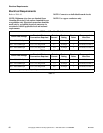
Electrical Requirements
47
M414038
© Copyright, Alliance Laundry Systems LLC – DO NOT COPY or TRANSMIT
Jumper Configuration Instructions
OPL Micro Control Models Only
Changing the transformer configuration jumper is
required if any of the following apply:
● You have 208 Volt service and are connecting a
gas or steam model rated for 208 Volt or
240 Volt.
● You have 415 Volt service and are connecting a
gas or steam model rated for 380 Volt or
415 Volt.
To configure your 208 Volt or 240 Volt tumbler for
208 Volt operation, you must remove the 240 Volt
configuration jumper located in the contactor box and
replace it with the 208 Volt jumper supplied with the
literature packet. This must be done prior to supplying
power to the machine. Failure to install proper
configuration jumper may result in damage to sensitive
electronic controls and may void warranty.
To configure your 380 Volt or 415 Volt tumbler for
415 Volt operation, you must remove the 380 Volt
configuration jumper located in the contractor box and
replace it with the 415 Volt jumper supplied with the
literature packet. This must be done prior to supplying
power to machine. Failure to install proper
configuration jumper may result in damage to sensitive
electronic controls any may void warranty.
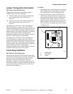
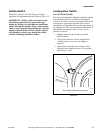
Ferrite Ring Installation
OPL Micro Control Models Only
The ferrite ring provided in the literature packet must
be installed over the power leads during connection of
electrical service. The ferrite protects the sensitive
electronic controls from destructive electrical
disturbances which may be present on power lines to
the machine. Failure to properly install the ferrite ring
may result in damage to the electronic controls and
will void control warranty.
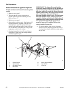
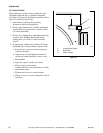
To Install:
1. Immediately after connection of power leads and
before applying power to machine, locate each of
the incoming service leads including ground.
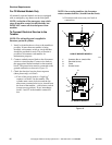
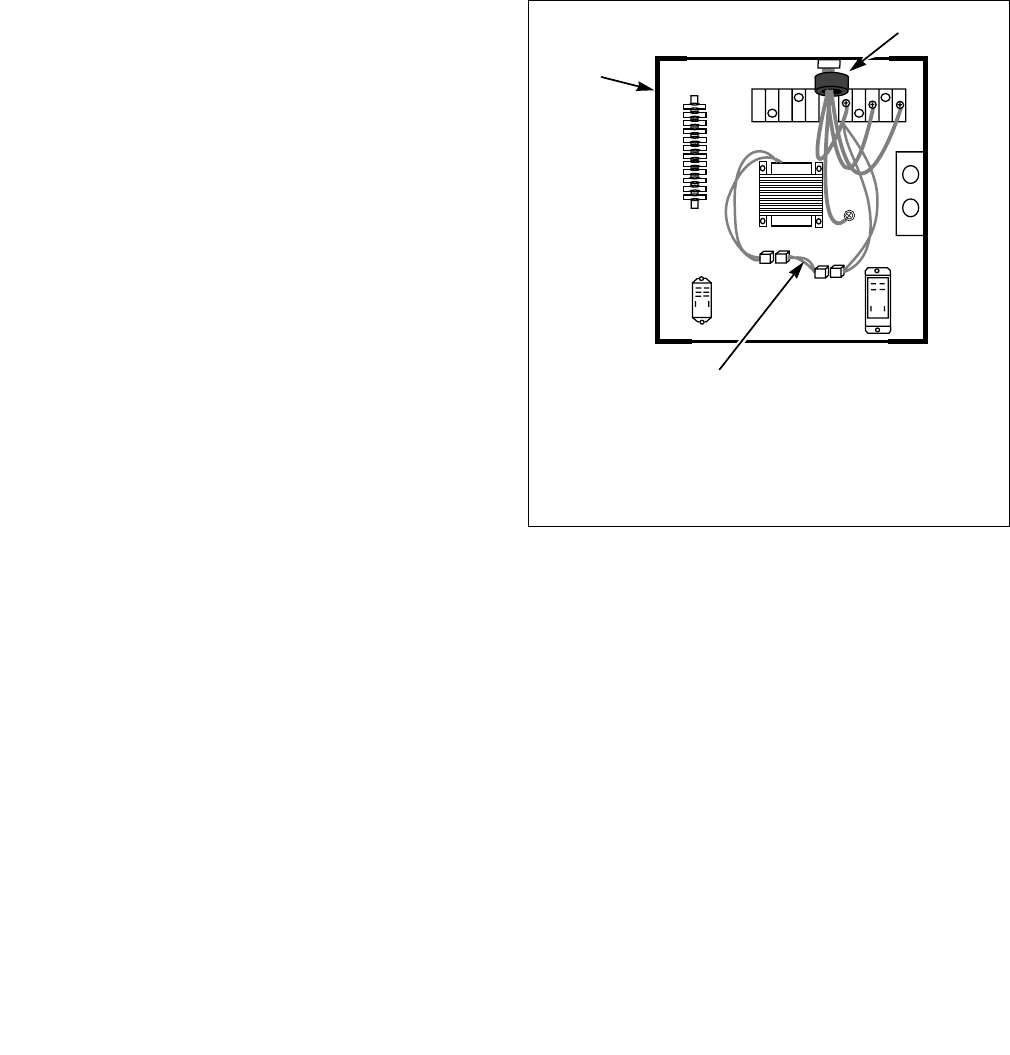
2. Snap the ferrite ring closed over all the service
leads inside of the contactor box as shown. It is
important that the ferrite ring be installed inside
the contactor box. Refer to Figure 19. Do not
install the ferrite outside of the box or other area.
Make sure that service leads are in the center of
the ferrite before closing the ring so not to pinch
or damage leads.
Figure 19
T225S
1 Contactor Box
2 Ferrite Ring
3 Jumper
T225S
1
2
3