


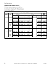
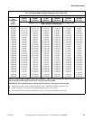
Electrical Requirements
M414038
46
© Copyright, Alliance Laundry Systems LLC – DO NOT COPY or TRANSMIT
For CE Marked Models Only
All manually operated models are factory-equipped
with an emergency stop button on the front panel.
NOTE: Activation of the emergency stop switch
stops all machine control circuit functions, but
DOES NOT remove all electrical power from
machine.
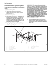
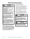
To Connect Electrical Service to the
Tumbler
NOTE: The wiring diagram is supplied in
literature packet in cylinder.
1. Install a circuit breaker as close to the tumbler as
possible. If more than one tumbler is being
installed, a disconnect switch or circuit breaker
should be provided for each. This will make it
possible to disconnect each tumbler for
maintenance purposes.
2. Connect conduit-encased leads to the disconnect
switch or circuit breaker. Connect wire leads to
the appropriate labeled terminal on the terminal
block. The ground wire must be connected to the
ground connection as shown in Figure 18.
3. Check the electrical service phase sequence
(three phase only) as follows:
a. If one of the power leads is a “high leg,”
connect it to lead L3 in the tumbler. The
cylinder must rotate clockwise and the fan
must rotate counterclockwise (as viewed from
the front of the tumbler – with selector switch
in non-reverse position). If not, interchange
leads L1 and L2 in the tumbler connection
box.
NOTE: On reversing tumblers, the fan motor
rotates counterclockwise (viewed from the front).
b. Disconnect and reverse any two leads at
connections.
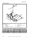
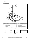
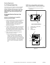
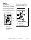
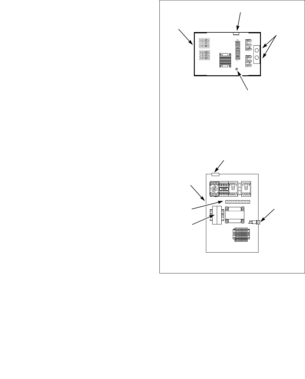
Figure 18
T390I
1 Contactor Box or Junction Box
2 Electrical Service
3 Fuses
4 Ground Screw
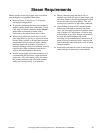
TMB1275N
T390i
1
2
3
4
NON-CE MARKED MODELS
TMB1275N
CE MARKED MODELS
1
2
3
3
4