


35
M414038
© Copyright, Alliance Laundry Systems LLC – DO NOT COPY or TRANSMIT
Gas Requirements
IMPORTANT: Any product revisions or conversions
must be made by the Manufacturer’s Authorized
Dealers, Distributors or local service personnel.
IMPORTANT: The installation must comply with
local codes or, in the absence of local codes:
● with the latest edition of the “National Fuel
Gas Code,” ANSI Z223.1/NFPA 54 in the
U.S.A.,
● with CSA-B149.1 Natural Gas and Propane
Installation Code in Canada,
● and Australian Gas Association/Australian
L.P. Gas Association requirements in
Australia.
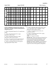
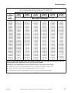
Obtain specific gas service pipe size from the gas
supplier. Refer to Table 7 for general pipe size.
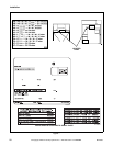
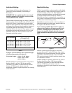
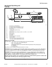
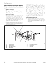
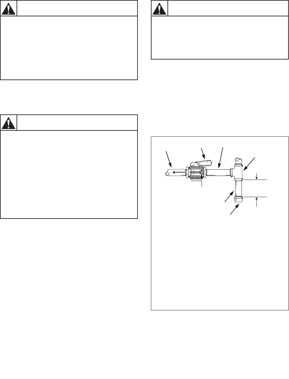
A dirt and water vapor pipe trap must be furnished and
installed by customer. Refer to Figure 13.
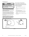
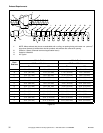
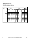
Install a 1 inch (25.4 mm) pipe gas loop to maintain
equal pressure at all gas connections. Refer to
Figure 14.
NATURAL GAS service must be supplied at 7.0 ±
1.5 inch water column pressure (1.74 ± 0.37 kPa).
L.P. (Liquefied Petroleum) GAS service must be
supplied at 11 ± 0.3 inch water column pressure
(2.74 ± 0.07 kPa).
EUROPEAN GASES – The above data for Natural
and L.P. Gas does not apply in the EU. Refer to
Installing Gas Drying Tumblers in the European
Union Section.
Figure 13
WARNING
To reduce the risk of fire or explosion, DO
NOT CONNECT THE GAS LINE TO THE
TUMBLER IF THE GAS SERVICE IS NOT
THE SAME AS THAT SPECIFIED ON THE
TUMBLER SERIAL PLATE! It will first be
necessary to convert the gas burner
orifice and gas valve. Appropriate
conversion kits are available.
W060
WARNING
The tumbler and its individual shut-off
valve must be disconnected from the gas
supply piping system during any
pressure testing of that system at test
pressures in excess of 1/2 psig (3.45 kPa).
The tumbler must be isolated from the
gas supply piping system by closing its
individual manual shut-off valve during
any pressure testing of the gas supply
piping system at test pressure equal to or
less than 1/2 psig (3.45 kPa).
W061
T135I
1 Gas Line to Tumbler Controls
2 Shut-Off Valve
3 Gas Supply Piping System
4 Gas “T” Fitting
5 6 in. (152 mm) Minimum Gas Pipe
6 Gas Pipe Cap
7 Dirt and Water Vapor Trap
8 1/8 in. (3.2 mm) NPT plugged tapping
accessible for pressure testing. Gauge
connection located upstream from tumbler
gas supply connection.
WARNING
To reduce the risk of fire or explosion, if
the tumbler is to be connected to
Liquefied Petroleum (L.P.) gas, a vent to
the outdoors must be provided in the
room where the tumbler is installed.
W062
T378I
1
2
3
4
5
6
7
8