


Gas Requirements
37
M414038
© Copyright, Alliance Laundry Systems LLC – DO NOT COPY or TRANSMIT
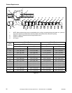
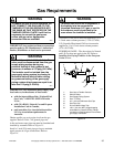
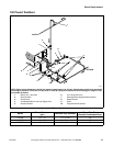
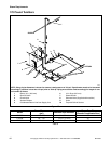
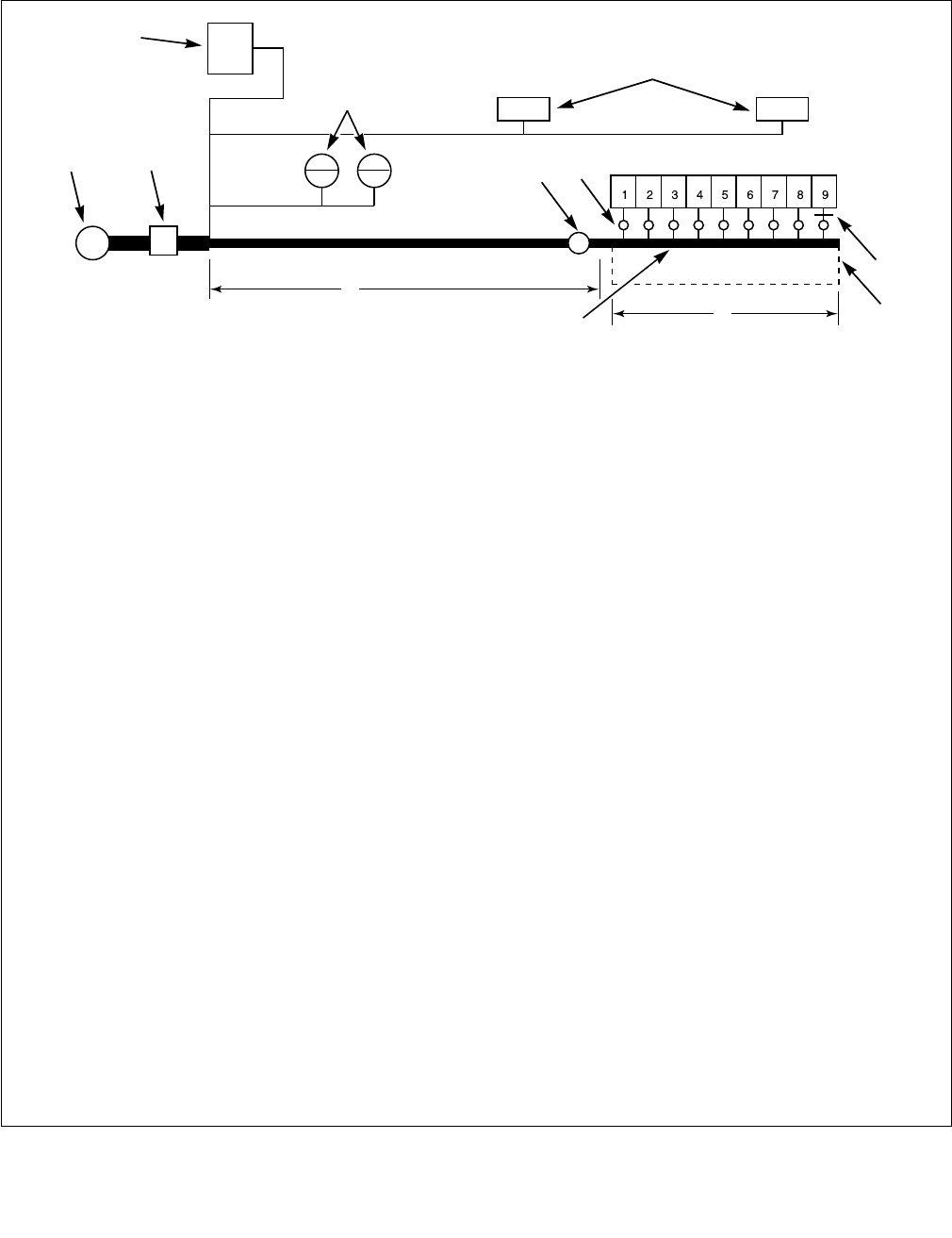
Gas Supply Pipe Sizing and
Looping
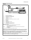
Figure 14
T494I
1 Gas Furnace (120,000 Btu/hr)
2 Gas Water Heaters (400,000 Btu/hr each)
3 Gas Space Heaters (70,000 Btu/hr each)
4 Pressure Tap
5 1 in. (25.4 mm) Gas Pipe Loop
6 19 ft. (5.8 m)’
7 Minimum Pipe Size to Tumbler is 3/4 in. for 120FG, 1 in. for 170FG
8 25 ft. (7.6 m)
9 Main Regulator
10 Gas Meter
11 Pressure Regulator (If required)
12 Shut-Off Valves
13 120 Pound Tumblers (300,000 Btu/hr each)
170 Pound Tumblers (395,000 Btu/hr each)
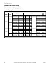
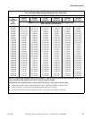
SAMPLE CALCULATIONS:
Equivalent length = Total length of main gas supply pipe to the far end of the tumblers.
= 25 ft. + 19 ft. (7.6 m + 5.8 m) gas supply pipe
= 44 ft. (13.4 m) total gas line
Total Btu/hr = The sum of the Btu/hr of all 120 pound tumblers being fed by the main gas supply pipe.
= 9 x 300,000
= 2,700,000 Btu/hr
Using Table 7, the main supply pipe diameter should be 3 in. (76 mm).
IMPORTANT: Gas loop piping must be installed as illustrated to equalize gas pressure for all tumblers
connected to single gas service. Other gas using appliances should be connected upstream from loop.
IMPORTANT: Line pressure must be maintained at 7 ± 1 water column inches (1.74 ± 0.23 kPa) for
Natural Gas (11 + 0.3 water column inches for L.P. [Liquefied Petroleum] Gas) (2.74 ± 0.07 kPa) with
all gas appliances running (tumblers, water heaters, space heaters, furnace, etc.).
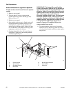
An in-line pressure regulator may be required on Natural Gas models if the line pressure exceeds 8 water
column inches (2.00 kPa) pressure with all gas appliances firing.
9
13
8
4
3
2
1
7
10
11
12
6
5