


Recessed area
and closet
installations
Fire Hazard
l
Dryers MUST be exhausted to
outslde.
Failure to do so may result in a fire.
l
Do Not exhaust dryers into a
chimney, furnace cold air duct,
attic or crawl space, or any other
duct used for venting.
Accumulated lint could result In a
fire or cause moisture damage.
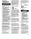
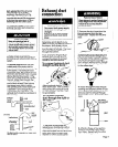
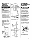
This appliance may be installed in
a recessed area.
The installation spacing is in the
minimum allowable. Additional
spacing should be considered for
ease of Installation, servicing, and
compliance with local codes and
ordinances.
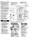
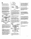
Unobstructed air openings are
required for laundry equipment
when door Is Installed. Door must
have two centered openings as
Illustrated. Both openings must
provlde a minimum of 72 square
Inches of unobstructed airflow
as shown.
Do Not block air bow at the bottom 1
I
front of the dryers with laundry or
rugs. Airpow from the bottom of
dryer Is needed for operating
efficiency.
I rO’
L
-
t
Additional
clearances for
wall, door and
floor moldings
,moyb
required or
If external
, exhaust elbow
is u
Closet vieqnr
Side view
,<
/
I
0’ -I,
ddiial
XC0 inlay be
eded for
xhausl elbow.
I,
I
0’
/Additional
clearances for
wall. door and
) floar moldings
may be
required.
closet
door
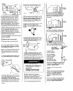
Companion appllatice y lacing
should be considered.
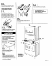
1 Product dimensions
Side View
door +
door
l/4’
-0pprox. 1’
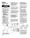
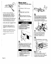
Co change to a
30, or 60-minute
:iming cam
Electrical Shock Hazard
Disconnxt both power supply
cords from the electric power
supply before making these
changes. Change timing cams
before completing electrical
connection.
Failure to follow these instructions ~
may result in electrical shock or
~ personal injury.
-Each dryer Is equipped with a 45
minute timer cam that provldes 45
mlnutes of drying time when
activated by the coin slide.
You can Install the 3Gmlnute or 60-
minute timing cam (shipped with
each dryer) as follows:
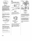
1. Unlock control panel. Lift up and
rotate out from cabinet. Control
panel will still be attached to
cabinet.
2. Reach into control panel area.
Use a Phillips screwdriver to loosen
(but not remove> timer mounting
bracket screw. Lift up to remove
timer assemble and bracket from
cabinet.
/ ratchet tooth
3. Turn the timing cam by hand until
the ‘V--shaped notch lines up
below the ratchet tooth.
Recessed front view
Page c