


Electrical
requirements.
OBSERVE AU GOVEdNlNG COdES
AND ORDINANCES.
.
.
.
.
.
.
.
.
.
F
c
I ”
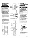
Electrical ground Is required on this
appliance.
If cold water pipe Is interrupted by
plastic, non-metallic gaskets, or
other insulating materials, Do Not
use for grounding.
Do Not ground to a gas pipe.
Do Not modify the power supply
cord plugs. iflplugs will not fit the
outlets, have proper outlets installed
by a qualified electrician.
Use new 30-ampere power supply
cord kits. Do Not reuse old power
supply cords. Possible electrical
shock or fire could occur if old
power supply cords are used.
Do Not have a fuse in the neutral or
grounding circuit. A fuse in the
neutral or grounding circuit could
result in an electrical shock.
Do Not use an extension cord with
this appliance.
Check with a qualified electrician if
you are in doubt as to whether the
appliance is properly grounded.
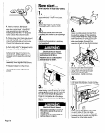
1 Do Not plug the power supply cords
(pigtails) into a live wail receptacle
before connecting the pigtails to the
dryer terminal blocks. Read ‘Direct
wiring connectton’. Pages 4 and 5
for detailed instructions.
:aiiure to follow these instructions
:ouid result in serious injury or death.
9’
m
th
*. It
ot
cc
a:
is
w
NI
cc
ttl
aI
SE
codes permit and a Separate ’
rounding wire Is used, it is recom-
lended that a eiectriclan determine
tat the grounding path Is adequate.
Is-tie personal responsibility and
3llgatlon of the customer to
Intact-a qualified electrlclan to
;ylr& that the electrlcai Installation
adequate and In conforjmance
WI Natlonal ElectrIcal Code ANSI/
FPA 70-jlatest edltlon. and all local
2des and ordinances. Allow sldck Iti
le line between the wall and the
Dpllance so that It can be moved if
rrvlclng is ever necessary.
ihis appliance must be connectec
to copper wlre only,
A 3/4’. U.L.-llsted strain relief must
be provided at each end of the
power supply cables (at the
appliance and at the Junctionbox).
Electrical Shock Hazard
1. A three-wire. slngie 1 Y-C+% 120/
240voit, &Hz, AC-on1 y, electrical
supply (or three-wire, ’ 20/208-volt if
spedfled on namepla tee> is
required on a separat 3.30-ampere
circuit, fused on both : Ides of the
line. (llme-deiay fuse <f clrcult
breaker ls recommenc ed.) The
wlrlng diagram is loca’ed l&de the
control panel and act ess panels.
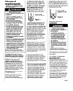
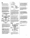
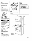
J-wire. 30-amp
recepL ~cie (IO-30R)
Figure 1
Typical Xl-ampere rece >tacle for use
where local codes pem It use of
flexible power supply cc rds (pIgtolls).
2. Local codes may pc ~rrnlt the USB of
U-L-Wed, 120/24&volt mlnlmum. 3G
ampere dryer power SI apply cord kits
(plgtails). The cords coltaln three.
No.-10 copper wires ar Id match
three-wire receptacles of NEMA
Type 1 G3OR, shown In I :gure 1.
Connectors on the dry x end must
be ring terminals or spc Ide terminals
with upturned ends. U L.-listed.
3/4’ strain reliefs must t 8 provlded at
the polnt the power su >ply cords
enter the appliance.
3. This appliance can t 8 connected
dlrecity to the fuse disconnect or
circuit breaker box thrcugh flexible
i armored or nonmetallic: sheathed,
lOgauge minimum, cc pper cable.
A 3/4’, U.L.-listed strain I elief must be
provlded at each end Df the power
1 supply cables (at the a Dpliance and
at the junction box).
4. For four-wire installat on, the
appliance wiring must x revised.
The appliance cabinet must not be
grounded to the neutrc II terminal.
must be connectec 1 to me
grounding wire (green: of the power
supply cords.
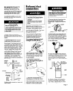
i When four-wlre receptc icles of NEMA
i Type 14-30R are used, (see Figure 2)
1 matching 120/240-volt nlnlmum, 3&
ampere, U.L.-listd dryc r power
supply cord kits (pigtall: #> must be
‘used. The cords contalr1 four, No.-10
copper conductors wit I ring terml-
nals or spade terminals wlth
upturned ends on drye end
tetmlnating In a NEW “.ype 14-30P
plug on supply end. The I fourth
(groundlng) conductor must be
: identified by a green OI green/
j yellow cover and the n, ?&al
CC onductor by a white cover. Cords
Sk
muld be Type SRD or SRDT, with
3,
/4’. U.L.-llsted strain reliefs and be at
le at 4 feet long. The four-wire power
sl apply cords and strain reliefs are not
P
rovlded with the dryers.
4-wire. JO-amp
receptacle
(14-JOB)
Figure 2
LIternate electrical
:onnection
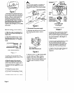
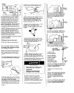
‘0 connect a separate
younding wire-
Jse grounding wire and clamp
lssembiy (Part No. 685463) or No.-10
Jauge mlnimum, copper grounding
rrire. Connect grounding wire to a
grounded cold water pipe’ with the
clamp and then to the external
grounding connector on the dryers.
Do Not ground to a gas supply pipe
or hot water pipe. Do Not connect
me power supply cords to electric
power supply until the dryers are
permanently grounded.
Eiectrlcal Shock Hazard
l
Electrical ground Is required on
.this appilance.
l
This appliance must be
connected to a grounded
metal. permanent wiring system;
or an equlpment-grounding
conductor must be run with
the circuit conductors and
connected to the equipment-
grounding terminal or lead on
the appliance.
l
Disconnect power supply cord
from the electric supply before
making these changes. Failure
to do so may result in personal
injury.
Failure to do so may result in
electrical shock or personal injury.
his appliance ls manufactured with
ie neutral terminal connected to
Cle cabinet.
Do
Not ground to &gas supply pipe
or hot water pipe, Do Not connect
the power supply cords to electric
power supply until the dryers are
permanently grounded.
Page 3