


B
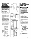
If loc:l codes DO NOT permit
cablnetgroundlng to the neutral
wires of the power supply cords:
1. Disconnect the power supply.
2. Attach a 3/4’. U.L.-lIsted straln relief
to each dryer through the power
supply cord hales. (See Figure 6.)
Ighten each straln relief firmly to the
cabinet. Place the power supply
cord or direct wire through each
strain relief. Tighten screws flrmly.
3.
Remove the grounding wires
(green wlth yellow stripes) from the
external groundlng connectors and
fasten under center, silver-colored
terminal block screws.
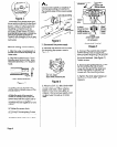
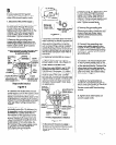
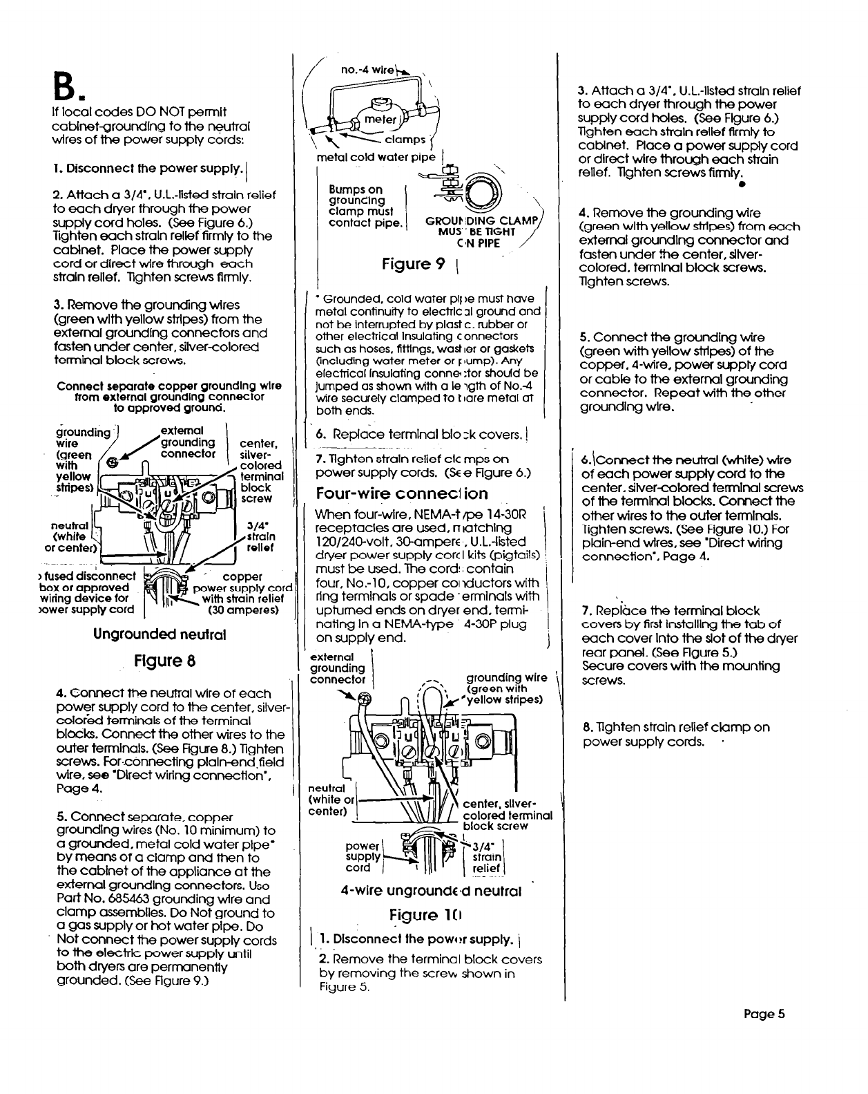
Connect separate copper groundlng wlre
from external grounding connector
to approved ground.
mower supply cord
Ungrounded neutral
Figure 8
4.
Connect the neutral wire of each
power supply cord to the center, silver-
color&d terminals of the terminal
blocks. Connect the other wires to the
outer termlnals. (See Fgure 8.) Tighten
screws. Forc6nnecting plaln-end,field
wire, see ‘Direct wiring connectlon’,
Page 4.
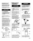
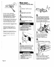
5. Connect separate, copper
groundlng wires (No. 10 minimum) to
a grounded, metal cold water pipe’
by means of a clamp and then to
the cabinet of the appliance at the
external groundlng connectors. Use
Part No. 685463 grounding wire and
clamp assemblies. Do Not ground to
a gas supply or hot water pipe. Do
Not connect the power supply cords
to the electric
power supply until
bath dryers are permanently
grounded. (See Figure 9.)
metal cold water pipe 1
Bumps on
grounllng
I
*cB
\
clamp must
contact pipe.
GROUF :DlNG CLAMP
MUS BE TIGHT
C’N PIPE
/
Figure 9 \
l
Grounded. cold water plj )e must hove
metal continuity to electric 31 ground and
not be interrupted by plast c. rubber or
other electrical Insulating connectors
such as hoses. fifflngs. wast ler or gaskets
(including water meter or F lump). Any
electrical Insulating tonne :tor should be
jumped as shown with a le igth of No.-4
wire securely clamped to t Iare metal at
both ends.
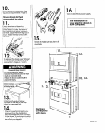
6. Replace termlnal blo zk covers. )
7. Tighten straln relief ck mps on
power supply cords. (SE e Flgure 6.)
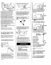
Four-wire conned ion
When fouriwlre, NEMA-t ape 14-30R
receptacles are used, n latching
120/240-volt, 3Uamperc , U.L.-listed
dryer power supply core I kits (pigtails)
must be used. The cord: contain
four, No.-1 0, copper COI lductors with
ring terminals or spade ‘ermlnals with
upturned ends on dryer end, termi-
nating In a NEMA-type 4-3OP plug
on supply end.
4-wire
ungroundcmd neutral .
Figure 1[1
1.
Disconnect the powder supply. i
2. Remove the terminal block covers
by removing the screw shown in
Figure 5.
3. Attach a 3/4’, U.L.-listed strain relief
to each dryer through the power
supply cord holes. (See Flgure 6.)
Tlghten each strain relief firmly to
cabinet. Place a power supply cord
or direct wlre through each strain
relief. Tlghten screws firmly.
l
4. Remove the grounding wire
(green with yellow stripes) from each
external groundlng connector and
fasten under the center, sitver-
colored. termlnal block screws.
llghten screws.
5. Connect the grounding wire
(green with yellow stripes) of the
copper. 4-wire. power suppbf cord
or cable to the external grounding
connector. Remt with the other
grounding wire.
&\Connect the
neutral (white) wire
of each power supply card to the
center, silver-colored terminal screws
of the terminal blocks. Connect the
other wires to the outer termlnals.
Tighten screws. (See Figure 10.) For
plain-end wires, see ‘Direct wiring
connection’. Page 4.
7. Red&e the terminal block
covers by first InstallIng the tab of
each cover Into the slot of the dryer
rear panel. (See Figure 5.)
Secure covers with the mounting
screws.
8. Tlghten straln relief clamp on
power supply cords.
.
Page 5