


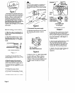
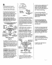
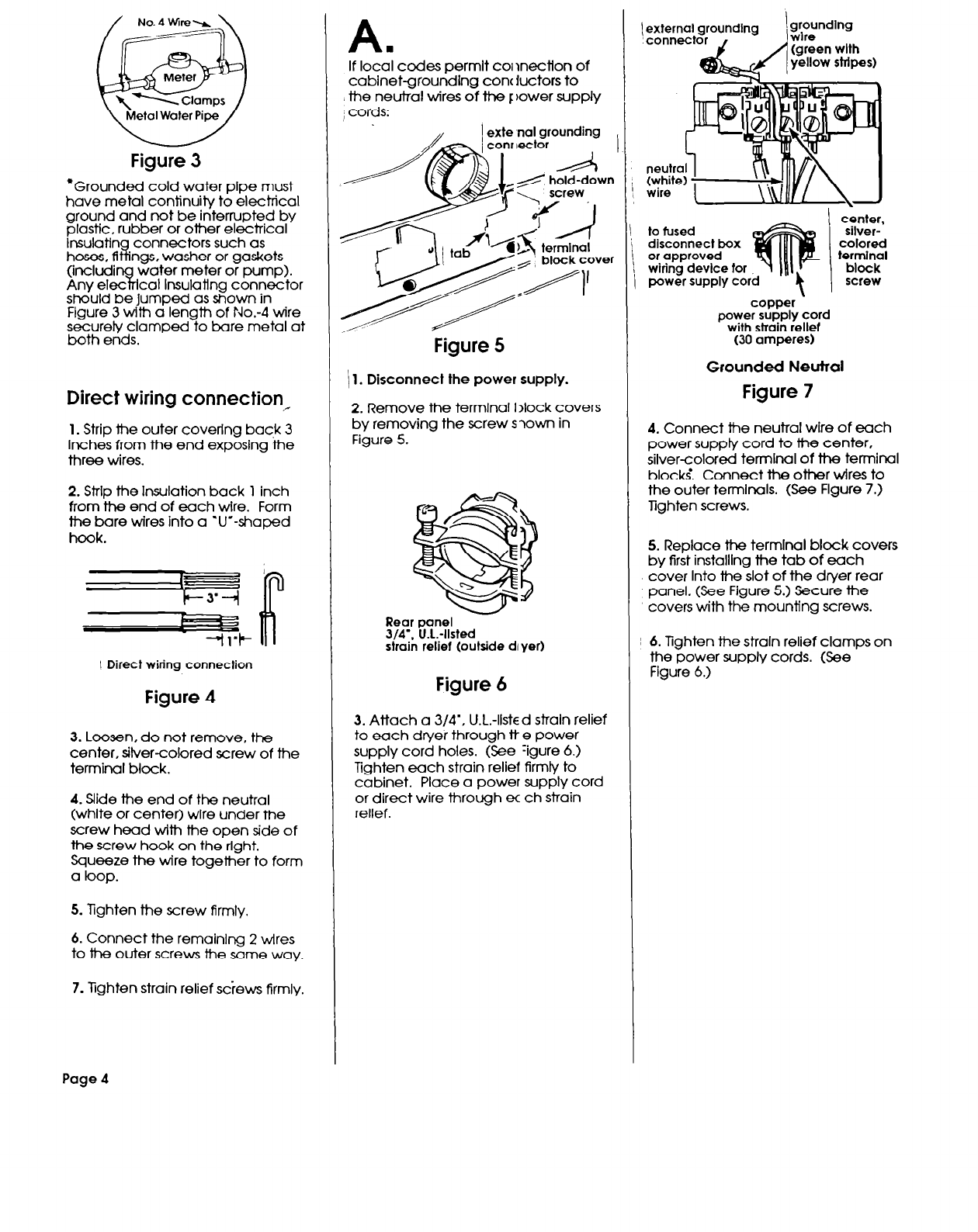
Figure 3
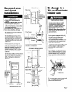
*Grounded cold water pipe must
have metal continuity to electrical
ground and not be interrupted by
plastic, rubber or other electrical
lnsulatin connectors such as
hoses, 8
i
ngs. washer or gaskets
(includi
water
7%
meter or pump).
Any elec cat Insulating connector
should be Jumped as shown in
Figure 3 with a length of No.-4 wire
securely clamped to bare metal at
bath ends.
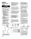
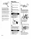
Direct wiring connection_
1. Strip the outer covering back 3
Inches from the end exposing the
three wires.
2. Strip the Insulation back 1 inch
from the end of each wire. Form
the bare wires into a V-shaped
hook.
I Direct wiring connection
Figure 4
3.
Loosen, do not remove, the
center, silver-colored xrew of the
terminal block.
4. Slide the end of the neutral
(white or center) wire under the
screw head with the open side of
the screw hook on the right.
Squeeze the wire together to form
a loop.
5. lighten the screw firmly.
6. Connect the remalnlng 2 wires
to the outer screws the same way.
7. Tighten strain relief screws firmly.
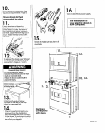
A.
If local codes permlt c01 lnection of
cabinet-grounding concjuctors to
the neutral wires of the F Bower supply
1 cords:
,,
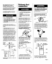
1 exte ,nal grounding
Figure 5
\ 1. Disconnect the power supply.
2. Remove the terminal I >lock covers
by removing the screw s ?own in
Figure 5.
Rear panel
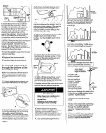
3/4’. VI.-llsted
strain relief (outside di yer)
Figure 6
3. Attach a 3/4’, U.L.-listed straln relief
to each dryer through tt e power
supply cord holes. (See -igure 6.)
Tighten each strain relief firmly to
cabinet. Place a power supply cord
or direct wire through ec ch strain
rellef.
gw;(;)eundlw
(green wlth
yellow stripes)
to fused
disconnect box
or approved
wiring device tor
power supply cord
center,
silver-
colored
termlnal
block
screw
copper -
power supply cord
with strain relief
(30 amperes)
Grounded Neutral
Figure 7
4. Connect the neutral wire of each
power supply cord to the center,
silvercolored termlnal of the terminal
block;. Connect the other wires to
the outer termlnals. (See Flgure 7.)
Tighten screws.
5. Replace the termlnal block covers
by first installlng the tab of each
cover Into tie slot of the dryer rear
panel. (See Figure 5.) Secure the
covers with the mounting screws.
6. Tighten the strain relief clamps on
the power supply cords. (See
Figure 6.)
Page 4