


SECTION V
SERVICING .............................................................................................................. 16
A. Computer Controls ................................................................................................................... 17
B. Ignition Controls ....................................................................................................................... 18
C. Thermostats .............................................................................................................................. 21
D. Sail Switch Assembly (Gas Models Only).................................................................................. 23
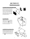
E. Front Panel and Main Door Assemblies ..................................................................................... 23
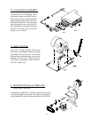
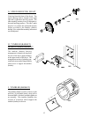
F. Pulleys ...................................................................................................................................... 25
G. Tumbler (Basket) Alignment ...................................................................................................... 28
H. Bearings ................................................................................................................................... 29
I. Basket and Support .................................................................................................................. 32
J. V-Belts ..................................................................................................................................... 32
K. Motors ..................................................................................................................................... 34
L. Impellor .................................................................................................................................... 35
M. Lint Drawer Assembly .............................................................................................................. 35
SECTION VI
TROUBLESHOOTING ........................................................................................... 37
SECTION VII
ELECTRICAL TROUBLESHOOTING ............................................................... 41
SECTION VIII
PHASE 6 OPL SYSTEM DIAGNOSTICS ........................................................... 42
A. Diagnostic (L.E.D. [light emitting diode] Display) Failure Codes ................................................. 42
B. L.E.D. (light emitting diode) Display Indicators .......................................................................... 44
C. Phase 6 OPL Microprocessor Controller Relay Output L.E.D. (light emitting diode) Indicators ... 45
SECTION IX
L.E.D. DISPLAY/CODES ........................................................................................ 46
A. L.E.D. (light emitting diode) Display Operating Status ................................................................ 46
B. Phase 6 OPL Microprocessor L.E.D. (light emitting diode) Displays .......................................... 47
C. L.E.D. Codes ........................................................................................................................... 48
D. Computer Logic and Wiring Diagram ........................................................................................ 49
SECTION X
TECHNICAL INFORMATION .............................................................................. 55
A. Motor Plate (High and Low Voltage)......................................................................................... 55
B. Data Label ............................................................................................................................... 56
C. Using a Manometer .................................................................................................................. 57
D. Tool List ................................................................................................................................... 58