


23
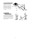
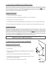
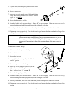
D. SAIL SWITCH ASSEMBLY (GAS MODELS ONLY)
The sail switch is a heat circuit safety device which controls the burner circuit only. When the dryer is operating
and there is proper airflow, the sail switch damper pulls in and closes the sail switch. Providing ALL the other
heat-related circuits are functioning properly, ignition should now be established. If an improper airflow occurs,
the sail switch damper will release, and the circuit will open.
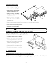
To Replace Sail Switch
1. Disconnect electrical power to the dryer.
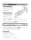
2. Remove the two (2) screws which hold sail switch box cover to sail switch box.
3. Disconnect the two (2) wires from the switch.
4. Disassemble sail switch from mounting bracket by removing the two (2) screws securing switch in place.
5. Reverse this procedure for installing new sail switch. Adjust sail switch as described in the next section.
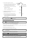
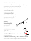
To Adjust Sail Switch
With the dryer operating at a high temperature setting, pull the sail switch away from the burner. The sail switch
should open and extinguish the burner. Let the sail switch damper return to the burner wall. The sail switch
should close to restart the burner ignition cycle. If the sail switch circuit does not operate as described, bend the
actuator arm of the sail switch accordingly until proper operation is achieved. To check proper open position of
sail switch, open main door, manually depress main door switch, and start dryer. With the main door open and the
dryer operating, the sail switch should be open, and the burner should not come on.
CAUTION: DO NOT abort this switch by taping or screwing sail switch damper to burner.
PERSONAL INJURY or FIRE COULD RESULT.
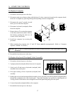
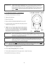
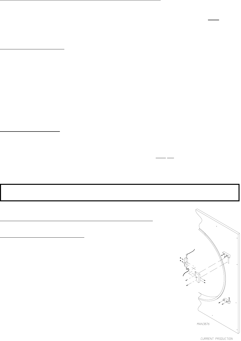
E. FRONT PANEL and MAIN DOOR ASSEMBLIES
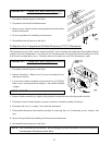
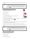
To Replace Main Door Switch
1. Discontinue electrical power to the dryer.
2. Open main door.
3. Remove the two (2) Phillips head screws holding the main door switch bracket
assembly in place.
4. Remove door switch bracket and disconnect wiring from switch.
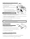
5. Disassemble door switch from bracket by removing the two (2) #6-32 nuts.
Remove door switch from bracket.
6. Reverse this procedure for installing new door switch.