


39
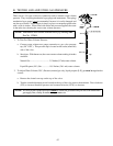
NOTE: In the following steps, when checking the voltage leave one of your meter leads attached to
terminal block #7 or any good ground connection.
NOTE: The following sections must be performed with the appropriate output light emitting diode
(L.E.D.) and appropriate L.E.D. indicator dots on.
1. Check for voltage across the two (2) black wires of the steam damper solenoid. You can check this voltage
at the J21 top basket (tumbler) connector or the J22 connector for the bottom basket (tumbler). If voltage
is present and damper is not opening, replace the solenoid.
2. Check for voltage across both terminals of the basket (tumbler) hi-limit switch. If voltage is present on both
terminals, check for bad wire or termination on the red wire from the basket (tumbler)
hi-limit switch through the J19 connector (top basket [tumbler]) or J20 connector (bottom basket [tumbler])
to the burner hi-limit switch. If voltage is present on only one (1) terminal of the basket (tumbler) hi-limit
switch, replace the basket (tumbler) hi-limit switch.
3. Check for the “heat out” voltage of the computer upper Dual Microprocessor Controller (DMC) connector
J1 pin #1 for the top basket (tumbler), or the lower DMC connector J2 pin #1 for the bottom basket
(tumbler). If voltage is present on the “heat out” pin of the computer, check for bad wire or termination on
the red wire from the computer “heat out” which passes through the I/O connector in the back of the
computer box to the basket (tumbler) hi-limit switch.
4. If no voltage, replace the computer.
F. “dOOr” Condition
NOTE: The following sections must be performed with the appropriate output L.E.D. and appropriate
L.E.D. indicator dots on.
NOTE: In the following sections, the voltage you are checking for is 24 VAC unless otherwise
specified.
NOTE: If the L.E.D. indicator dot is on and the appropriate L.E.D. output light is not on, replace
computer.
NOTE: If the display reads “dOOr,” this indicates that there is an open circuit in the computer’s door
switch circuit. This fault display involves the door switch, the computer, the transformer, the
lint drawer switch, or the harnesses. If the L.E.D. input light on the component side of the
computer is on and you are getting the “dOOr” code, replace the computer.
1. Remove the wires from the door switch and check for continuity while pushing down the plunger of the
switch. If no continuity, replace door switch. If continuity, reassemble connections onto the switch.
2. Repeat the same process as in Step #1 for the lint drawer switch.
3. Check for voltage across terminal block #2 and #7. If no voltage is present, replace the 24 volt transformer.