


37
Telephone: (508) 678-9000
Fax: (508) 678-9447
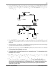
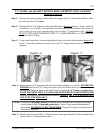
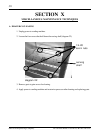
Step 4: Remove the U.V. sensor probe assembly from the unit.
Step 5: Prior to the replacement of the new U.V. sensor probe assembly clean the quartz window of the
replacement U.V. sensor with a commercial scale remover (such as Lime-Away or CLR) on a high
quality lint-free cotton swab. When using an acidic solution (scale remover) for cleaning, follow the
manufacturer’s directions for safety. Inspect the window visually to insure that it is clean, clear and
dry.
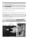
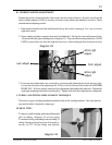
Step 6: Inspect the rest of the U.V. sensor probe and the metal fitting it inserts into. Perform any other
required cleaning prior to the U.V. sensor probe replacement. Do not attempt to tighten, loosen or
open the sealed U.V. sensor probe. Contamination or loss of function may result.
Step 7: Reconnect the U.V. sensor probe interface board along with the temperature sensor plug to the
relay board.
Step 8: Electrical subassembly cover replacement reverse (step 1, parts A through C).
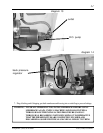
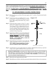
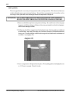
Step 9: Assemble the U.V. sensor probe into the U.V. chamber. Tighten the brass nut finger tight (an additional
1/4 turn may be necessary).
Step 10: Replace the temperature sensor (flat side towards the chamber). It is required to replace the clip
and acorn nut to hold the U.V. sensor harness along with the temperature sensor firmly against the
U.V. chamber. Tighten with a 7/16” wrench.
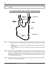
Step 11: Restore the water supply and check for leaks.
Step 12: Reestablish power to the unit, check the green monitor light on the side of the case for a stead glow.
NOTE: The alarm buzzer will sound for a few seconds until U.V. lamp and quartz sleeve reaches operat-
ing conditions.