


113231-4 www.amdry.com 27
INSTALLATION
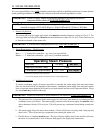
1. Water Supply:
The fire suppression system must be supplied with a minimum water pipe size of 1/2” and be provided with
40 psi +/- 20 psi (2.75 bar +/- 1.37 bar) of pressure. For use of optional manual bypass, a second source
with the same piping and pressure requirements is required.
If the rear area of the dryer or the water supply is located in an area where it
will be exposed to
cold/freezing temperatures, provisions must be made to protect these water lines from freezing.
WARNING: If the water in the supply line or water solenoid valve freezes, the fire suppression system
will be INOPERATIVE!!
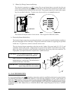
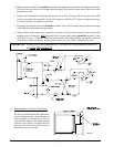
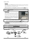
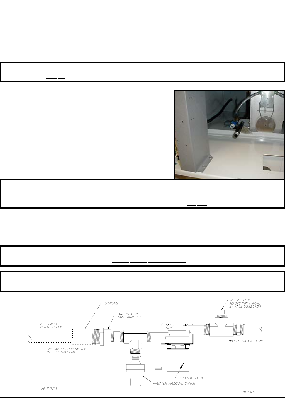
2. Water Connections:
The water connection is made to the 3/4”-11.5 NH hose
adaptor of the electric water solenoid valve, located at the
rear upper midsection of the dryer (refer to the photograph).
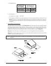
The water solenoid valve has a 3/8” M.P.T. connection
supplied with a 3/4”-11.5 NH hose adaptor to provide the
minimum 1/2-inch supply (feed) line. Flexible supply line/
coupling must be used in an effort to avoid damaging the
electric water solenoid valve.
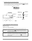
NOTE: The 3/4”-11.5 NH is a standard hose coupling screw thread. It is not to be confused with
3/4” N.P.T. The sealing of an NH connection is made with a washer opposed to the mating
threads of an N.P.T. assembly. The two (2) thread designs are not compatible.
It is recommended that a filter or strainer be installed in the water supply line.
Flexible 1/2 feeds must be provided to avoid damage to electric water solenoid valve by vibration.
IMPORTANT: Flexible supply line/coupling must be used. Solenoid valve failure due to hard
plumbing connections WILL VOID WARRANTY.
IMPORTANT: Appliance is to be connected to the water mains using a new hose set and the old
hose set should not be reused.
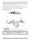
Typical Water Supply
Water Solenoid Valve
&