


24 American Dryer Corp. 113231-4
MAN2497
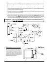
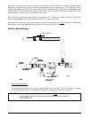
d. Shutoff valves for each dryer should be installed in the supply line, return line, and drip trap return line.
This will allow the dryer to be isolated from the supply main and the return main if the dryer needs
maintenance work.
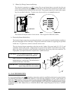
e. Install an inverted bucket steam trap and check valve at least 12-inches (30.48 cm) below the steam
coil as close to the coil as possible. A trap with a capacity of 700 lb (317.51 kg) of condensate per hour
at 125 psi (8.62 bar) is needed for each unit.
f. The supply line and the return line should be insulated. This will save energy and provide for the safety
of the operator and maintenance personnel.
g. Water pockets in the supply line, caused by low points, will provide wet steam to the coil possibly
causing steam coil damage.
ALL horizontal runs of steam supply piping should be pitched 1/4-inch
(6.35 mm) for every 1 foot (0.31 meters) back towards the steam supply header causing the condensate
in the line to drain to the header. Install a bypass trap in any low point to eliminate wet steam.
IMPORTANT: Flexible hose/coupling must be used. Coil failure due to hard plumbing connections
will VOID THE WARRANTY.
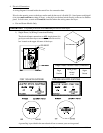
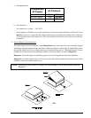
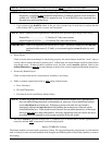
4. Steam Damper Air System Connections
The dryer is manufactured with a pneumatic
(piston) damper system, which requires an
external supply of compressed air. The air
connection is made to the steam damper
solenoid valve, which is located at the rear
inner top area of the dryer just in front of
the electric service relay box.