


Exhaust Requirements
31
70256801
© Copyright, Alliance Laundry Systems LLC – DO NOT COPY or TRANSMIT
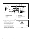
Manifold Venting
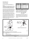
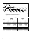
While it is preferable to exhaust tumblers individually
to the outdoors, a main collector duct may be used if it
is sized according to
Figure 12. This illustration
indicates minimum diameters, and should be increased
if the collector length exceeds 14 feet (4.2 meters) and
two 90° elbows. The diameter of a round duct must be
increased by 10% for each additional 20 feet
(6.1
meters). Cross sectional area of a rectangular or
square duct must be increased 20% for each additional
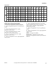
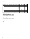
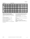
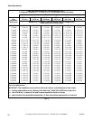
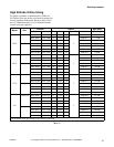
20 feet (6.1 meters). Refer to
Table 8 to determine
equivalent ducting sizing. The collector duct may be
rectangular or square in cross section, as long as the
area is not reduced. Provisions MUST be made for lint
removal and cleaning of the collector duct.
The vent collector system must be designed so the
static back pressure measured 12 inches (305 mm)
from the exhaust outlet does not exceed the maximum
allowable pressure specified on the installation sticker
on the rear of tumbler. Static back pressure must be
measured with all tumblers vented into the collector
operating.
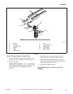
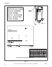
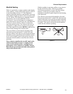
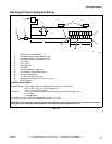
Never connect a tumbler duct at a 90° angle to the
collector duct. Refer to
Figure 11. Doing so will
cause excessive back pressure, resulting in poor
performance. Never connect two tumbler exhaust
ducts directly across from each other at the point of
entry to the collector duct.
With the tumbler in operation, airflow at any point in
the duct should be at least 1200 feet per minute
(366
meters per minute) to ensure that lint remains
airborne. If 1200 feet per minute cannot be
maintained, schedule a regular inspection and cleaning
of the ductwork.
The collector system must be designed so the static
back pressure measured 12 inches (305 mm) from the
exhaust outlet does not exceed the maximum allowable
pressure specified on the installation sticker on the rear
of tumbler. This must be measured with all tumblers
vented into the collector operating.
Figure 11
T438I
T438i