


Installation
70256801
22
© Copyright, Alliance Laundry Systems LLC – DO NOT COPY or TRANSMIT
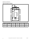
Basic Configuration
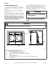
1. Determine the necessary conversion operations
to convert from the factory-supplied
configuration to the desired configuration.
2. Perform the conversions required so the machine
is properly configured for the desired country and
gas (refer to Specific Conversion Procedures
Section):
● How to Convert Gas Valve from Regulated to
Unregulated
NOTE: Conversion from regulated to unregulated
is only needed when regulated tumblers were
ordered, but unregulated tumblers were needed.
● How to Change Injector (Orifice) Size
● How to Adjust Gas Valve Governor/Regulator
3. If applicable, peel off the appropriate country
sticker from Part No. 503382 (included with
machine) and apply it to the serial plate over the
existing country information. Refer to
Figure 9.
4. If applicable, peel off the appropriate conversion
sticker from Part No. M413800 (included with
machine) and apply it to the serial plate over the
“ADJUSTED FOR ______ GAS: ______”
information. Refer to
Figure 9.
Figure 5
Specific Conversion Procedures
How to Convert Gas Valve from Regulated to
Unregulated
NOTE: Conversion from regulated to unregulated
is only needed when regulated tumblers were
ordered, but unregulated tumblers were needed.
Johnson G96 Gas Valve:
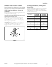
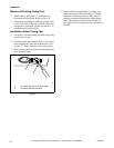
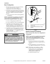
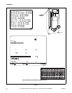
a. Disconnect electrical power from tumbler.
Close gas shut-off valve to tumbler. Refer to
Figure 5.
b. Follow instructions in Conversion Kit, Part
No. M400763 (Johnson Part No. Y71AA-5C).
NOTE: This kit does not contain any orifices.
c. Change injector size as required by the
appropriate table according to How to
Change Injector (Orifice) Size.
d. Commission tumbler for use.
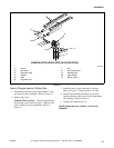
WARNING
When converting the tumbler to a
different gas or pressure, first verify that
the supply inlet pressure is equipped with
a pressure regulator (located ahead of the
tumbler) that will maintain the gas supply
at the inlet pressure specified.
W430
T103K
1 Gas Shut-Off Valve (Ahead of pressure tap)
2 Pressure Tap
3 Gas Shut-Off Valve (Shown in closed
position)
SPECIFIED
LOCAL INLET
PRESSURE
3
2
1