


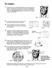
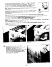
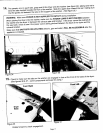
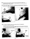

22.Rotate access panel into position, and securewith white or almond screws supplied in the
miscellaneousparts package. (See figure 51.) Removeprotective film from fascia and tape from
edges of control panel. (See figure 52.)
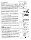
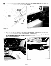
23.Removewasher and dryer timer knobs from miscellaneousparts package and insert them on the
respectiveshafts. NOTE: Timer shafts are differentbetween the washer and dryer. (See figure 53.)
.....
!
Figure 51
Figure 53
Figure 52
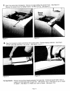
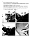
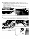
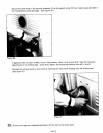
24. For nonalcove installations (where there is access to the rear of the appliance):
Plug in powercordforthe washerand dryer.
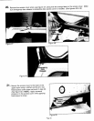
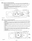
Removethe 2 outerscrews inthe backof the cabinetclosestto the sides (see figure 54) and secure
the securitybrackets(2) to the uppercabinet. NOTE: Slottedhole is orienteddown. (See figure 55.)
Do nottightenuntilthe next step is completed.
Cabinet Screw Cabinet
Screw
Figure 54 Figure55
Page 21