


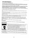
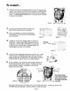
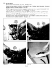
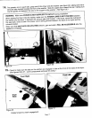
For gas dryers apply joint compound or about 1-1/2 wraps of Teflontape _ 1
over threaded connectionon the end of the gas pipe. (See figure 17.)
1
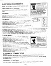
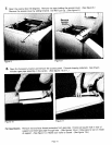
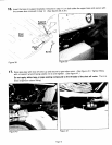
An elbow is recommended,for additionaldepth, pointing down to allow
the unit to be located further back into the alcove. (See figure 18.)
Note: Pipejoint compound must be resistantto the action of any liquefied
petroleum gas.
Add additionalfitting to connect the 3/8 inch gas pipe to a female threaded
end of a 3/4 inch flexible connector making sure the connection is tight. Figure 17
(See figure 19.)
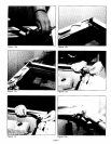
Makesure the shutoffvalve on the end of the gas pipe is closed andconnectto the gas supply.
Open gas service valve and check all gas supply connections from service valveto shutoff valve for
leaks using a soap solution, DO NOT use an open flame to check for
gas leaks. If bubbles occur,tighten the connections and recheck.
NOTE: As a courtesy, many local gas utilitieswill inspect a gas appliance installation. Check with your
local utility to see if this service is provided in your area.
NOTE: The minimum permissiblegas (natural or mixed) supply pressure for purposes of input
adjustmentis 4.5 inches of water.
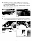
Figure 18 Figure 19
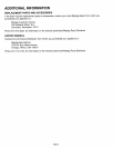
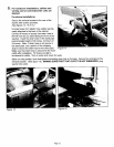
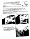
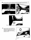
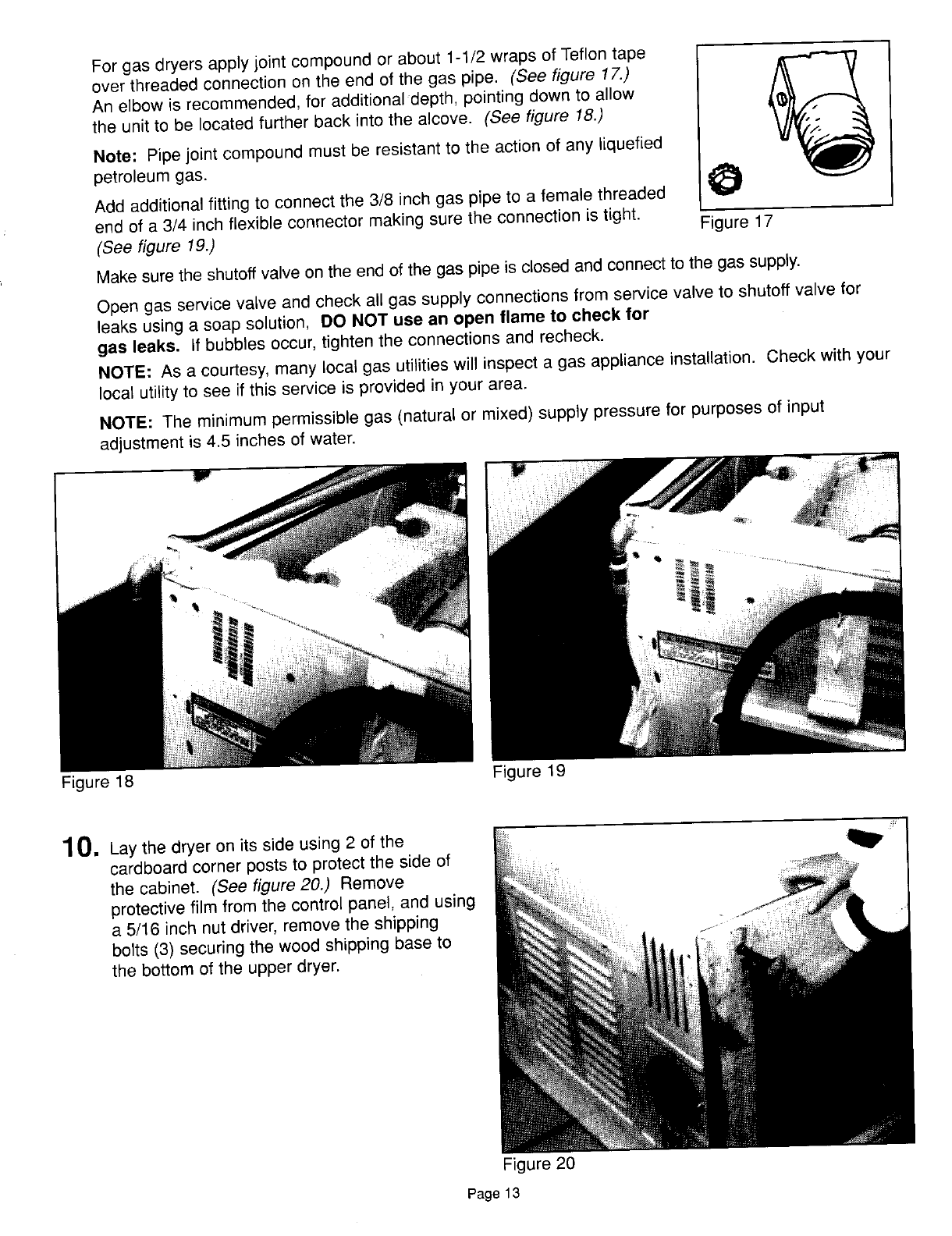
1 0, Lay the dryer on its side using 2 of the
cardboard corner posts to protect the side of
the cabinet. (See figure 20.) Remove
protectivefilm from the control panel, and using
a 5/16 inch nut driver, removethe shipping
bolts (3) securing the wood shipping base to
the bottom of the upper dryer.
Figure 20
Page 13