


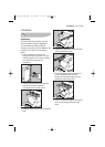
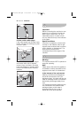
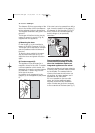

The distance (B) from upper edge of the
door to the centre of the hole depends
on the adjacent furniture's dimensions.
The required dimensions are given in the
picture C.
The hinges will be fixed to the door by
means of screws for wood (2-Fig. B)
supplied with the appliance.
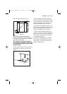
c) Mounting the door
Fix the hinges (1) to the machine by
means of the M5x15 screws (3-Fig. B).
The hinges can be adjusted to compen-
sate for possible uneven thickness of
the door.
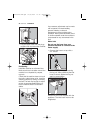
To align the door perfectly it is neces-
sary to loosen the screw (3-Fig. B),
adjust the door and tighten the screw
again.
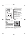
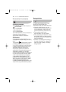
d) Counter-magnet (6)
The appliance is pre-arranged for a
magnetic closure of the door. To enable
a correct operation of this device, it is
necessary to screw the counter-magnet
(6) (steel disk + rubber ring) into the
inner side of the door.
Its position must correspond to the
magnet (4) on the appliance (see picture
D).
P0984
6
4
D
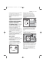
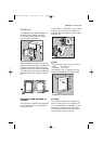
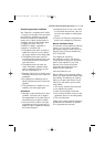
If the door has to be opened from left to
right, invert the position of the plates (7),
the magnet (4) and the plate (5) (Fig. B
and E). Mount the countermagnet (6)
and the hinges (1) as previously
described.
Recommendations regarding the
construction and fitting of a base
when the installation requires an
integrated appliance to be raised.
Where the appliance has been raised by
mounting onto a wooden base provided
by the installer. The material used to
construct the base should have a non
slip surface, be water repellent and if
possible be one solid piece.
If it is not possible to use one solid
piece, due to the additional height
required, ensure that any additional
strips of timber are glued and screwed
to the underside of the base (see Fig. F).
4
6
5
1
2
3
7
E
P0983
40 electrolux building-in
132973260 EN.qxd 07/05/2007 15.18 Pagina 40