


70
EMERGENCY STOP (E-Stop) SWITCH --- PB6
If the EMERGENCY STOP (E-Stop) switch (pendant) does not respond:
c. PROBABLE CAUSES;
1) ANOTHER EMERGENCY STOP (E-Stop) BUTTON
2) A DISCONNECT PLUG
3) FAULTY SWITCH
4) WIRING BACK TO TB1
d. POSSIBLE SOLUTIONS;
1) Verify that ALL other EMERGENCY STOP (E-Stop) buttons are not pushed in, and retest.
2) Verify that ALL of the Pendants disconnect plugs are indeed connected. The disconnect plugs are
for removal of the Pendant arm for shipping.
3) With the control voltage off, open pendant assembly and check switch using an OHM meter, replace
if defective.
4) Locate terminals 14 and 15 on TB1 on the bottom of the electrical enclosure. Open their associated
disconnects and place an OHM meter across these terminals. Push the EMERGENCY STOP
(E-Stop) button in. Does the OHM meter respond?
If YES, wiring from the pendant to TB1 is correct, check wiring on the main electrical panel,
then retest.
If NO, wiring from the TB1 is incorrect. Check wiring using the appropriate wiring diagrams
listed above, and retest.
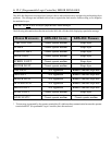
E. TEMPERATURE SENSING
INTRODUCTION
There is one (1) temperature sensing and controlling device in the ADS-464 located in the intake exhaust. The
temperature sensing devices are RTDs (Resistive Temperature Devices), whose resistance changes with
temperature information from each RTD is forwarded to a respective 4 to 20 milliampere (4 to 20 mA) transmitter
located on the Main Electrical Enclosure Panel. The converted signal is then connected to the PLCs analog
input module for further processing.
The following information will provide a means to respond to Temperature Sensing malfunctions, and verify
ALL its electrical signals. Refer to the following diagrams placement and wiring information.
ADS-464 ANNUNCIATOR, PENDANT, and UPPER RTDS WIRING DIAGRAM
ADS-464 MAIN PANEL WIRING DIAGRAM
ADS-464 SYSTEM BLOCK DIAGRAM