


16 American Dryer Corp. 113409-2
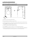
NOTE: When the exhaust ductwork passes through a wall, ceiling, or roof made of combustible materials, the
opening must be 2-inches (5.08 cm) larger than the duct (all the way around). The duct must be
centered within this opening.
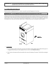
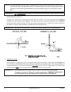
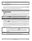
Outside Ductwork Protection
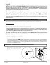
To protect the outside end of the horizontal ductwork from the weather, a 90° elbow bent downward should be
installed where the exhaust exits the building. If the ductwork travels vertically up through the roof, it should be
protected from the weather by using a 180° turn to point the opening downward. In either case, allow at least twice
the diameter of the duct between the duct opening and the nearest obstruction.
IMPORTANT: DO NOT use screens, louvers, or caps on the outside opening of the exhaust ductwork.
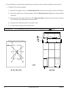
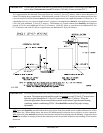
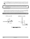
3. Multiple Dryer (Common) Venting
If it is not feasible to provide separate exhaust ducts for each dryer, ducts from individual dryers may be channeled
into a “common main duct.” The individual ducts should enter the bottom or side of the main duct at an angle not
more than 45° in the direction of the flow and should be spaced at least 55-3/4” (141.61 cm) apart. The main duct
should be tapered, with the diameter increasing before each individual 18-inch (45.72 cm) duct is added.
IMPORTANT: The dryer is not provided with a back draft damper. When exhausted into a multiple
(common) exhaust line, a back draft damper must be installed at each dryer duct.
IMPORTANT: No more than three (3) dryers should be connected to one (1) main common duct.
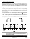
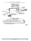
The main duct may be any shape or cross-sectional area, as long as the minimum cross section area is provided.
The illustration on page 18 shows the minimum cross section area for multiple dryer round or square venting.
These figures must be increased 10 square inches (64.52 square centimeters) when rectangular main ducting is
used, and the ratio of duct width to depth should not be greater than 3-1/2 to 1. These figures must be increased
in proportion if the main duct run to the last dryer to where it exhausts to the outdoors is unusually long (over 15 feet
[4.57 meters]) or has numerous elbows (more than three [3]) in it. In calculating ductwork size, the cross-sectional
area of a square or rectangular duct must be increased twenty percent (20%) for each additional 20 feet (6.09
meters). The diameter of a round exhaust must be increased ten percent (10%) for each additional 20 feet (6.09
meters). Each 90° elbow is equivalent to an additional 40 feet (12.19 meters) and each 45° elbow is equivalent to
an additional 20 feet (6.09 meters).
IMPORTANT: For extended ductwork runs, the cross section area of the ductwork can only be increased to
an extent. Maximum proportional ductwork runs cannot exceed 15 feet (4.57 meters) more
than the original limitations of 15 feet (4.57 meters) with three (3) elbows. When the
ductwork approaches the maximum limits as noted in this manual, a professional heating,
ventilating, and air-conditioning (HVAC) firm should be consulted for proper venting
information.
IMPORTANT: Exhaust back pressure measured by a manometer in the exhaust duct must be no less than 0
and must not exceed 0.6 inches (1.48 mb) of water column (W.C.).