


© Copyright, Alliance Laundry Systems LLC – DO NOT COPY or TRANSMIT
Operation
F232201
14
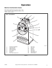
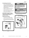
The shaft seal assembly includes a collar held in place
on the cylinder shaft with setscrews. The collar has a
flange with a ceramic ring which makes contact with a
spring-loaded face seal enclosed in a housing. The
collar contains two internal O-rings which maintain
contact with the cylinder shaft.
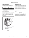
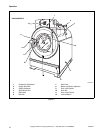
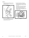
The polypropylene supply dispenser is mounted on the
right side of the washer-extractor, viewed from the
front. The dispenser has five supply compartments,
numbered 1–5, starting from the rear of the machine.
The compartments hold plastic supply cups that are
used for either liquid or dry supplies. A nozzle flushes
supplies from the cups with water for the time
programmed in the cycle.
Liquid supplies can be injected directly into the cups
by a customer-supplied external chemical supply
system. Five hose strain reliefs on top of the supply
dispenser facilitate connection to an external supply
system. A terminal strip inside a compartment
attached to the left side of the control module, viewed
from the rear of the washer-extractor, provides
connection points for external supply signals.
Emergency Stop Button
A red emergency stop button is located on the control
panel. Push the button in to stop the washer-extractor
in emergency situations. Turn button to the right and
pull out to reset.
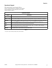
Drain Steps
Models that display WE-6 Firmware ID Code
“ARWCO1” and later or “HRWC18” and later (i.e.
“HRWC19”) after power up have two additional drain
steps called “WASH DRAIN” and “Drain 5.” The
steps provide a potential reduction in total cycle time
because steps are shorter.
“WASH DRAIN” is used for draining to the sewer
(“main” drain [drain 1]) when a spin step does not
follow a “WASH DRAIN.” Any other steps (for
example, fill step) may be programmed after a
“WASH DRAIN” step.
“DRAIN 5” is identical to a “DRAIN 1” step, except it
does not attempt to rebalance the load. “DRAIN 5” is
recommended before a medium spin, a lower speed
spin or a spray rinse step. Refer to Programming
manual for additional details.
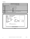
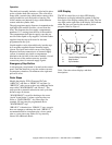
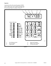
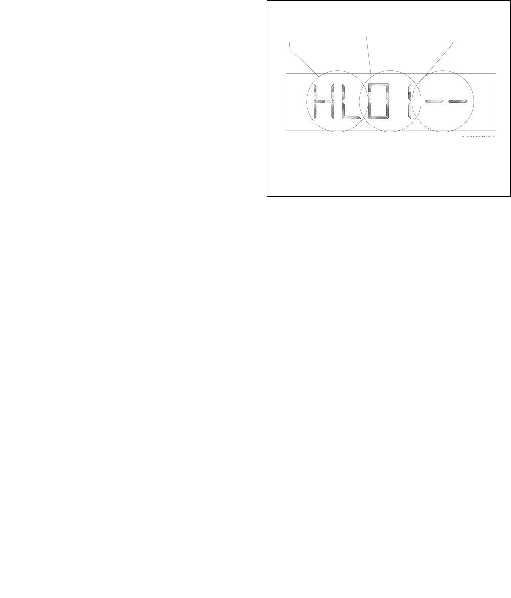
LED Display
The WE-6 control has a six-digit LED display.
References to display indications pertain to the first
four digits of the display reading left to right. The last
two digits on the right side of the display will indicate
either the last cycle used or the current cycle in
progress. Refer to Figure 5.
Figure 5
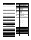
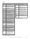
Table 1 lists the various displays and their
descriptions.
MC007A
1 Function Being Executed
2 Step Number
3 Cycle Number
1
2
3