


© Copyright, Alliance Laundry Systems LLC – DO NOT COPY or TRANSMIT
Operation
13
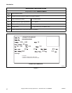
F232201
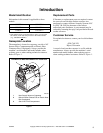
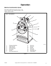
Theory of Operation
The design of the washer-extractor emphasizes
performance reliability and long service life. The
cylinder, shell, and main body panels are fabricated of
stainless steel.
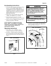
Electrical controls for the washer-extractor are housed
in a separate enclosure located on the top of the
machine. Removing the screws from the module
cover, lifting the cover, and pulling to the rear
provides access to the control module. This module
contains the WE-6 control, contactors, water-level
switch, and other control components.
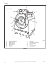
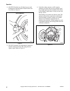
The cylinder is driven by a V-drive system supported
via the shaft by two flange-mounted spherical roller
bearings bolted to the A-frame.
The cylinder is constructed with four lifters or ribs that
lift the laundry from the bath solution when the
cylinder rotates at slow speed and then allow the
laundry to tumble back into the bath. This mechanical
action accomplishes the washing function. The
cylinder is perforated, allowing the water to drain from
within during the wash and extract steps.
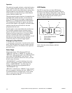
The spray rinse feature consists of a fiber-reinforced
clear hose connected to the center of the door glass and
to both a hot and cold water inlet valve. A
hemispherically-shaped spray nozzle inside the door
glass produces a fan-action water spray which
disperses rinse water throughout the load.
All UWPV washer-extractors use an AC inverter drive
control which provides seven preset motor speeds
using a single motor. The AC drive interface board
converts motor logic from the WE-6 control to the
correct signals for the AC inverter drive. In addition,
all logic inputs to the control are routed through this
board.
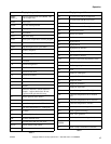
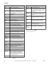
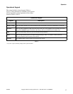
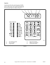
The operator can select from among 39 preprogrammed
cycles. Cycle 39 is a test cycle used to verify proper
operation of the washer-extractor. With the exception
of Cycle 01, the remaining cycles are complete wash
cycles or specialty cycles designed to handle various
fabrics at specific water temperatures and levels.
Cycle 01 is designed to test an external chemical
injection supply system.
Programmable custom cycles are another feature of
the UWPV.
The vibration switch system utilizes a micro-switch
mounted between the faces of the A-frame to signal
the WE-6 control that the load imbalance is too great
for high extract speeds. Depending on the design
series, the vibration switch will perform in either of
two ways. If the washer-extractor utilizes ONLY the
vibration switch to detect an out-of-balance load, the
switch will signal the WE-6 control to slow the motor
speed, allowing the load to re-distribute, and then
resume the spin speed programmed. The control will
attempt to redistribute the load in this manner up to
three times. On the third attempt, if an imbalance
condition is still detected, the control will abort the
spin speed step(s) and advance to the next non-spin
speed step.
However, if the washer-extractor is equipped with
BOTH the vibration switch and the AC inverter drive
balance detection systems, the function of the switch is
slightly different. The inverter drive will monitor load
imbalance conditions and the control. If the load is not
balanced to spin at the programmed spin speed,
control will attempt to re-distribute the load. After
three unsuccessful attempts to balance the load,
control will limit the spin speed (on models with the
WE-6 Firmware ID Code of “ARWCxx” the WE-6
display will alternately flash the programmed spin
speed and the substituted spin speed). During the spin
step, if the vibration switch detects a severe imbalance,
due to improper installation or improper loading of the
washer, the control will abort the remaining portion of
the cycle and stop the machine. The display will flash
“BAL/DR” while aborting the cycle until the door has
been opened.
Water enters the washer-extractor through
electromechanical water valves controlled by the
microcomputer. The microcomputer also controls the
drain and the door lock. In addition, it selects the water
levels according to the programmed cycle. Vacuum
breakers are installed in the water-inlet plumbing to
prevent backflow of water.
The standard production UW35PV and UW60PV use
a single drain valve. (Dual drains are available as an
option.) The UW80PV, UW100PV, UW125PV and
UW150PV use dual drain valves. The dual drains open
and close together under control of the WE-6 control.
The drain valve is normally open, which means that it
closes only when power is applied, thus allowing the
machine to drain in the event of a power failure.
A door-lock system prevents opening of the stainless
steel door when a cycle is in progress. It also prevents
operation of the washer-extractor when the door is
open. The door box contains the door-lock
microswitch, door-closed magnetic switch, and the
door-unlock solenoid.
On later design models equipped with a rotation
sensor, the door lock system will allow door to unlock
soon after basket stops at the end of the cycle.