


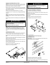


22 American Dryer Corporation 450431-3
bURNER CONTROL FAIL – This routine monitors the ignition
control’s gas valve output response. If the valve output signal
is not present from the ignition control within the valve time
limits the Phase 6 microprocessor controller (computer)
determines the ignition control has failed. If this occurs
when the cycle is active the machine will display “bURNER
CONTROL FAIL.” If the tumbler temperature is above 100º F
(38º C) the machine will continue to display “bURNER
CONTROL FAIL.” The machine will run with no heat for 3
minutes or until the temperature drops below 100º F (38º
C). If the tumbler temperature is below 100º F (38º C) upon
failure the machine will shut down and display “bURNER
CONTROL FAIL” with an audio indication.
bURNER FLAME FAIL – This routine allows 2 flame out retries
to occur before proceeding into the error. The count of 2 will
be established every time the call for heat was to occur.
Only if it reaches the count of 2 before the tumbler temperature
has reached the set temperature will this error be triggered.
The machine will run with no heat for 3 minutes or until the
temperature drops below 100º F (38º C). If the tumbler
temperature is below 100º F (38º C) upon failure, the
machine will shut down and display “bURNER FLAME FAIL”
with an audio indication. This process will occur every time
the heat output is active.
MAIN DOOR – This monitors the door circuit. If the machine
was not active and the main door was opened the display
would read “REAdY.” If a program attempt was made with
the main doors open the display will read “MAIN dOOR” with
an audio indication. If the machine is active and the main
door was opened the display would read “MAIN dOOR” with
no audio indication and the dryer will shut down. Once the
main door has closed the display would read “PRESS
START” press the “ENTER/START” key and it will continue
the programmed cycle.
LINT dOOR – This monitors the lint drawer and door circuit.
If the machine was not active and the lint drawer and door
was opened the display would read “REAdY.” If a program
attempt was made with the lint drawer and door open the
display would read “LINT dOOR” with an audio indication. If
the machine is active and the lint drawer and door was
opened the display would read “LINT dOOR” with no audio
indication and the dryer will shut down. Once the lint door
was closed the display would read “PRESS START” press
the “ENTER/START” key and it will continue the programmed
cycle.
TEMP SENSOR FAIL CHECK TEMP SENSOR FUSE – This
routine monitors the tumbler temperature. When the
temperature sensor or fuse opens with the machine not
active the display will read “TEMP SENSOR FAIL CHECK
TEMP SENSOR FUSE” with an audio indication. If the
machine was active at the time that the temperature sensor
or fuse opened the display would read “TEMP SENSOR
FAIL CHECK TEMP SENSOR FUSE.” The display will
continue to read “TEMP SENSOR FAIL CHECK TEMP
SENSOR FUSE” an audio indication will sound for
approximately 5-seconds, every 30-seconds until the
problem is corrected or the power to the dryer is
disconnected (and the problem is corrected).
NOTE: Once the Phase 6 microprocessor controller
(computer) detects a problem in the heat circuit, it
updates every 30-seconds, so that if the problem was a
loose connection in the circuit, which corrected itself, the
“TEMP SENSOR FAIL CHECK TEMP SENSOR FUSE”
condition would automatically be cancelled and the
display will return to “REAdY.”
ROTATE SENSOR FAIL – Indicates a rotational sensor circuit
failure meaning that there is a fault somewhere in the
tumbler rotating circuit, or the Phase 6 OPL microprocessor
controller (computer) program related to this circuit (program
location 2) is set incorrectly. In the active mode it should be
(ROTATE SENSOR ACTIVE), if the dryer is not equipped with
the optional rotational sensor it should be set in the
nonactive mode (No ROTATE SENSOR).
NOTE: RPM – This routine monitors the timing response
from the existing rotational sensor input and derives a
RPM measurement. To display this RPM measurement
(press the “ENTER/START” key once and release, then
press the “ENTER/START” key a second time and hold.
This will display the RPM measurement). The rotational
sensor must be active for operation of this feature.
CHECK MAIN FUSE – Indicates that the circuit fuse protection,
which is located on the back side of the Phase 6
microprocessor controller (computer) the display would
read “CHECK MAIN FUSE.” If the display continues after
the fuse has been replaced then it is the fault of the Phase
6 microprocessor controller (computer).
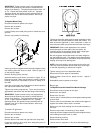
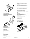
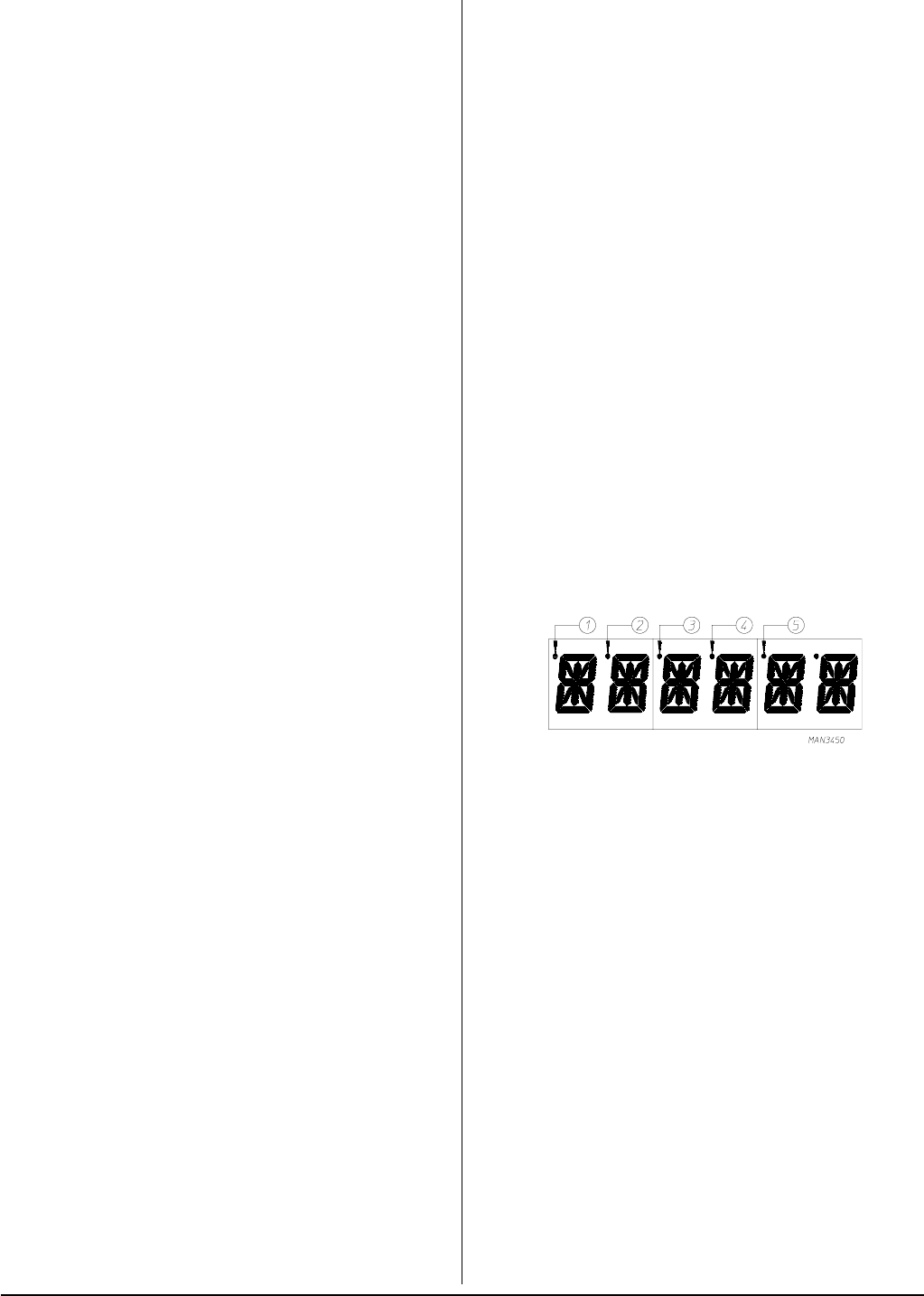
L.E.D. Display Indicators
The L.E.D. indicator dots located on the top portion of the
display indicate the various Phase 6 OPL computer output
functions while a cycle is in progress. These indicator dots
(as shown in the illustration below) do not necessarily
mean that the outputs are functioning. They are only
indicating that the function output should be active (on).
L.E.D. Display Indicator Number 1
For Optional Reversing Models:
This indicator dot is on when the drive (tumbler) motor is
operating in the forward mode (clockwise direction).
L.E.D. Display Indicator Number 2
For Optional Reversing Models:
This indicator dot is on when the drive (tumbler) motor is
operating in the reverse mode (counterclockwise direction).
L.E.D. Display Indicator Number 3
Heat Circuit Indicator:
This indicator dot is on whenever the Phase 6 OPL
microprocessor controller (computer) is calling for the
heating circuit to be active (on).
L.E.D. Display Indicator Number 4
On Indicator
This indicator dot is on whenever a cycle is in progress.
Additionally, when the Anti-Wrinkle program is active, the
indicator dot will be on whenever the Phase 6 OPL
microprocessor controller (computer) is in the Guard On
Time program.