


450431-3 www.amdry.com 11
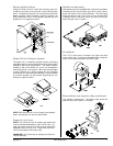
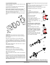
To Replace Microprocessor Temperature Sensor Probe
Discontinue electrical power to the dryer.
Remove lint drawer. Remove six screws securing lint door
and remove lint door.
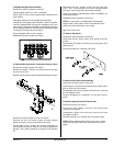
Remove microprocessor sensor bracket assembly from dryer.
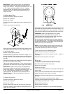
To Replace Keypad Label Assembly
Discontinue electrical power to the dryer.
Unplug keypad ribbon from rear of computer.
Slowly peel off and remove keypad label assembly from
control panel.
Peel paper backing off new keypad label assembly.
Holding the new keypad label assembly close to the panel,
insert the keypad ribbon through the rectangular slot in the
control panel. Align label assembly into position by matching
the red viewing window on the label to the rectangular cutout
in the panel and gently press into place.
Connect keypad ribbon to the computer.
Reestablish electrical power to the dryer.
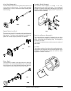
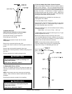
Disconnect the two “orange” wires from the high heat
(225° F [107° C]) thermostat, and remove modular bracket
connector, wires, and probe from bracket assembly.
Install new sensor probe assembly (ADC P/N 880251) by
reversing procedure.
Reestablish electrical power to the dryer.
NOTE: If, when power is reestablished, the computer
display reads “Temp Sensor Check Temp Sensor Fuse,”
check for a loose connection in the wiring.
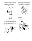
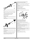
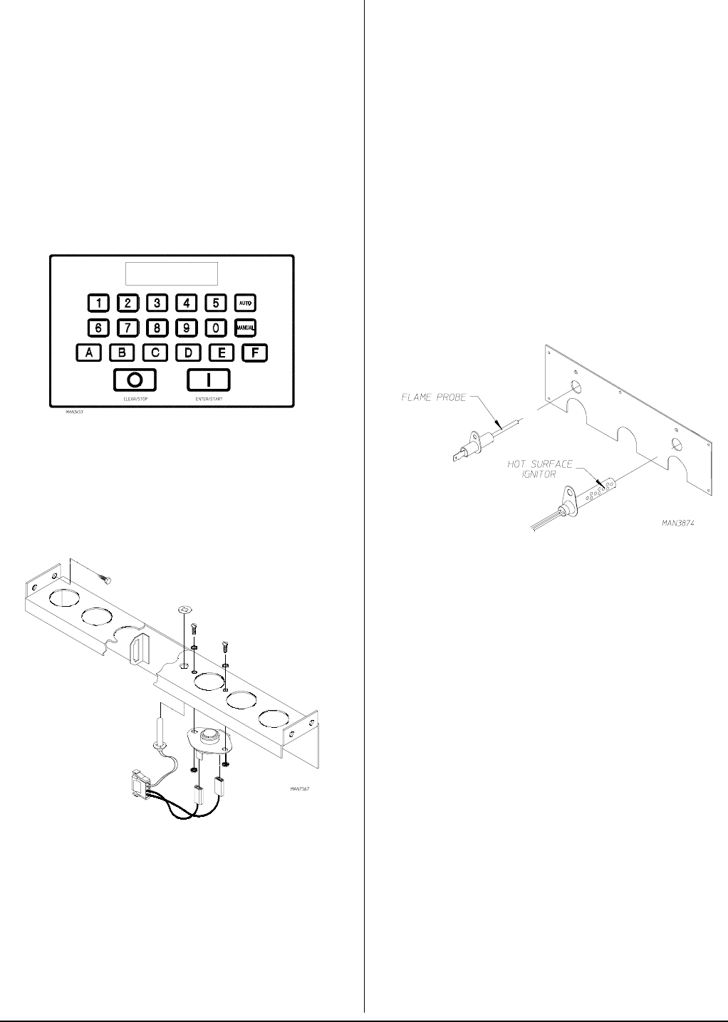
Ignition Controls
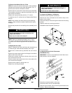
To Remove HSI Ignitor
Discontinue electrical power to the dryer.
Disconnect the two “white” ignitor wires going to the HSI
module.
Disassemble HSI ignitor from burner by removing the self-
tapping screw.
Reverse procedure for installing new ignitor.
Disconnect sensor bracket harness connector.
Remove the four Hex head screws securing bracket
assembly to dryer and remove bracket from dryer.
Disassemble sensor probe from bracket assembly by
removing the top push-on fastener securing the probe from
bracket. Use a small screwdriver to slowly pry the fastener
off.
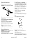
To Remove HSI Flame-Probe Assembly
Discontinue electrical power to the dryer.
Disconnect the “red” wire from the flame sensor probe, which
goes to S2 on the HSI module.
Disassemble flame sensor probe from burner by removing
the self-tapping screw.
Reverse procedure for installation of new flame sensor
probe.
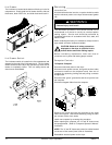
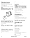
To Replace Spark Ignitor and Flame-Probe
Discontinue power to the dryer.
Disconnect high voltage connector and flame-probe
connection from ignitor.
Disassemble ignitor from burner by removing the two
self-tapping screws.
Reverse procedure for installing the new ignitor probe.
NOTE: Before reestablishing power to the dryer, visually
check the following: (refer to the illustration on the next
page).