


14 American Dryer Corporation 450431-3
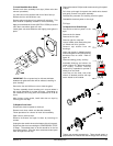
Discontinue electrical power to the dryer.
Remove lint drawer. Remove two screws securing lint door
and remove lint door.
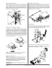
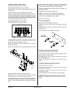
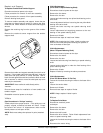
Locate sensor bracket assembly and the four Hex head
screws securing bracket assembly to the tumbler wrapper.
Disconnect sensor bracket harness connector and remove
bracket assembly from dryer.
Disconnect the two “orange” wires from the thermostat.
Disassemble thermostat from bracket assembly by removing
the two mounting screws, washers, and nuts.
Reverse this procedure for installing a hi-heat protector
thermostat.
Reestablish electrical power to the dryer.
NOTE: This is a manual reset thermostat. Before
changing the thermostat make sure the reset button is in to
determine if the thermostat has failed.
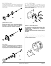
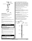
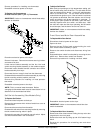
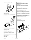
Sail Switch Assembly (Gas Models Only)
To Replace Sail Switch
Disconnect electrical power to the dryer.
Remove the two screws which hold sail switch box cover to
sail switch box.
Disconnect the two wires from the switch.
Disassemble sail switch from mounting bracket by removing
the two screws securing switch in place.
Reverse this procedure for installing new sail switch. Adjust
sail switch as described in the next section.
Reverse procedure for installing new thermostat.
Reestablish electrical power to the dryer.
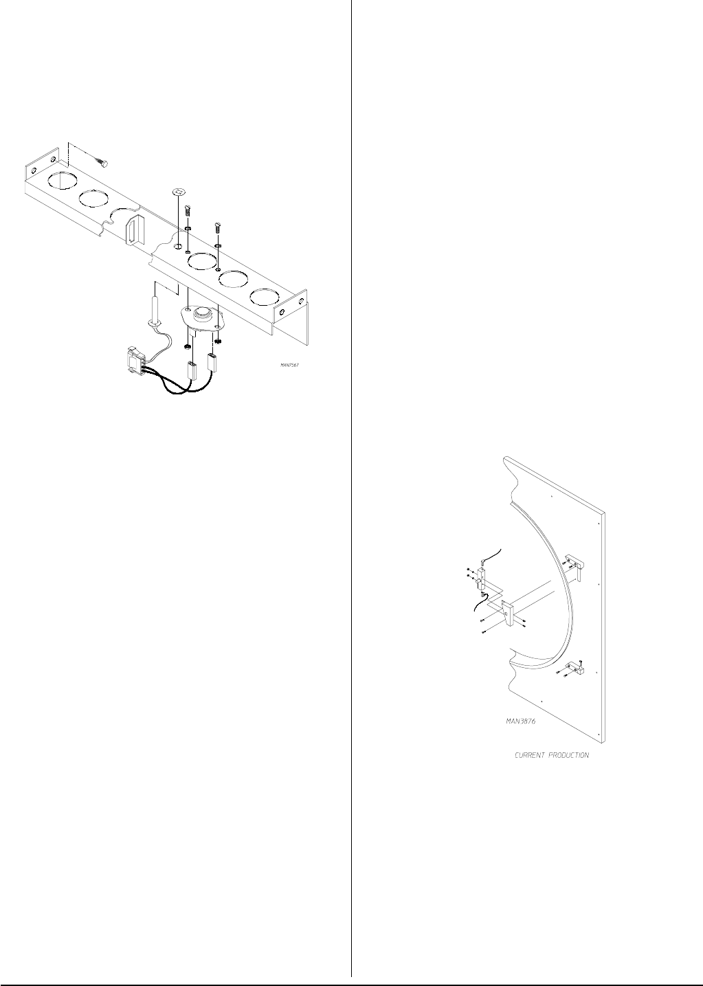
To Replace Lint Compartment
Hi-Heat Protector (225° F [107° C) Thermostat
IMPORTANT: Under no circumstances should heat safety
devices be disabled.
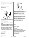
To Adjust Sail Switch
With the dryer operating at a high temperature setting, pull
the sail switch away from the burner. The sail switch should
open and extinguish the burner. Let the sail switch damper
return to the burner wall. The sail switch should close to
restart the burner ignition cycle. If the sail switch circuit does
not operate as described, bend the actuator arm of the sail
switch accordingly until proper operation is achieved. To
check proper “open” position of sail switch, open main door,
manually depress main door switch, and start dryer. With
the main door open and the dryer operating, the sail switch
should be open, and the burner should not come on.
IMPORTANT: Under no circumstances should heat safety
devices be disabled.
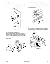
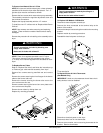
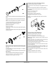
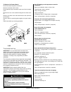
Front Panel and Main Door Assemblies
To Replace Main Door Switch
Discontinue electrical power to the dryer.
Open main door.
Remove the two Phillips head screws holding the main
door switch bracket assembly in place.
Remove door switch bracket and disconnect wiring from
switch.
Disassemble door switch from bracket by removing the two
#6-32 nuts. Remove door switch from bracket.
Reverse this procedure for installing new door switch.
Reestablish electrical power to the dryer.
IMPORTANT: Under no circumstances should the door
switch be disabled.
To Replace Main Door Assembly
Remove two Allen head screws holding the top main door
hinge block to the front panel.
Remove the main door by lifting up and off of bottom hinge
block.
Reverse this procedure for reinstalling new main door
assembly.