


12 American Dryer Corporation 450431-3
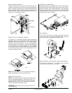
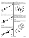
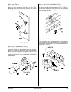
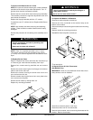
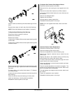
To Replace Gas Valve
(Refer to burner illustration on the next page)
Discontinue electrical power to the dryer.
Close shutoff valve(s) in gas supply line.
Disconnect gas valve wiring.
NOTE: Identify location of each wire for correct
reinstallation.
Break union connection before gas valve.
Loosen and remove screws (4) securing pipe brackets to
burner.
Remove gas valve/manifold assembly from dryer.
Remove valve mounting bracket, manifold, and piping from
gas valve.
Reverse procedure for installing new gas valve.
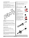
To Replace Main Burner Orifices
Refer to “To Replace Gas Valve” and follow the steps until
manifold is removed then unscrew main burner orifices and
replace.
NOTE: Use extreme care when removing and replacing
orifices. These orifices are made of brass and are easily
damaged.
Reversing the removal procedure for reinstalling.
▲ WARNING
!
Test all connections for leaks by brushing on a
soapy water solution.
Never test for leaks with a flame!!!
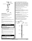
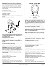
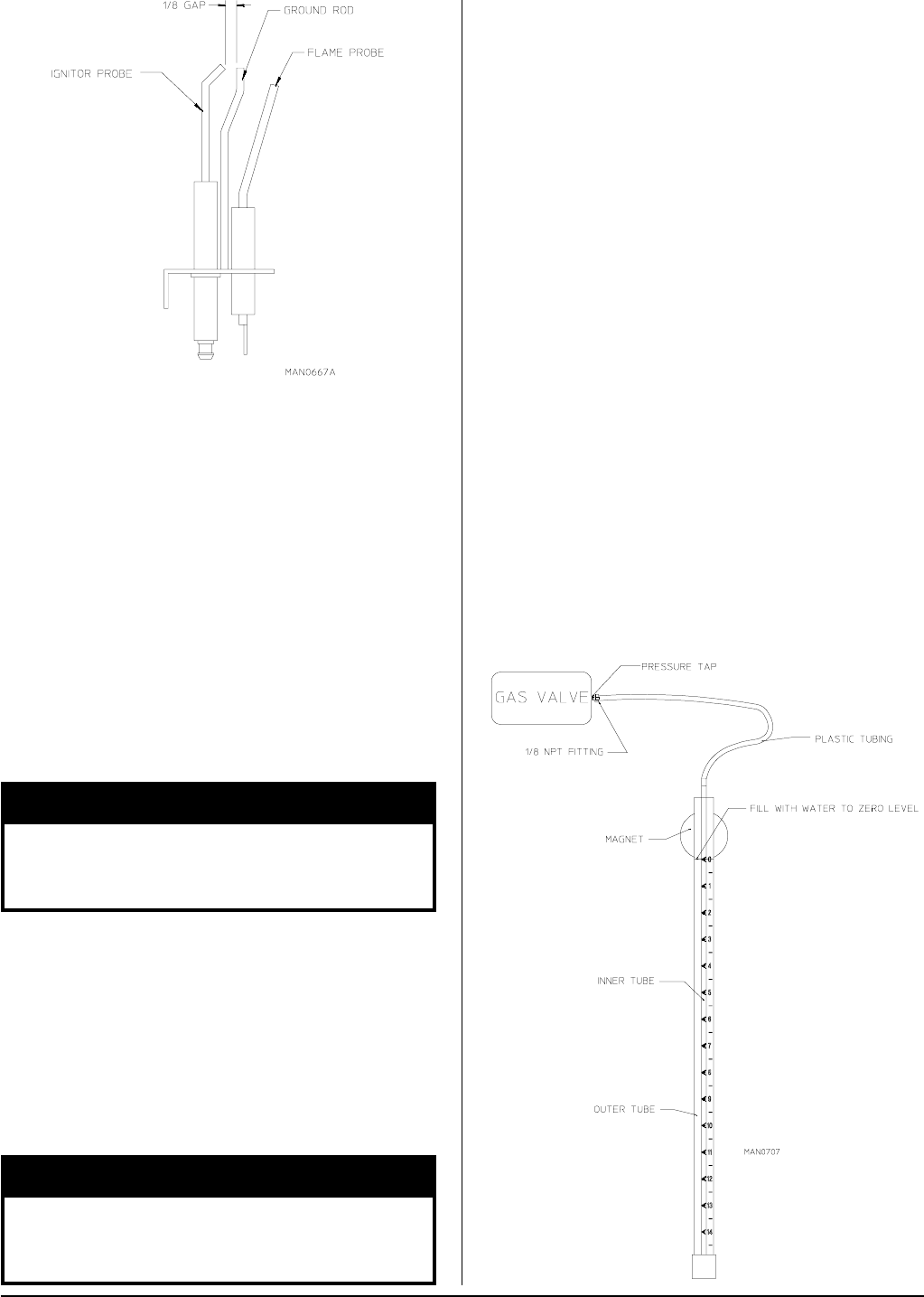
To Test and Adjust Gas (Water Column) Pressure
There are two types of devices commonly used to measure
water column pressure. They are spring/mechanical-type
gauges and manometers. The spring/mechanical-type gauge
is not recommended, because it is easily damaged and not
always accurate. A manometer is simply a glass or
transparent plastic tube with a scale in inches. When filled
with water and pressure applied, the water in the tube rises
showing the exact water column pressure.
NOTE: Manometers are available from the factory by
ordering ADC P/N 122804.
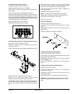
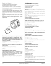
To Test Gas Water Column Pressure:
Connect water column test gauge connection to gas valve
pressure tap (1/8” N.P.T.). This pressure tap is located on
the outlet (manifold) side of the valve.
Start dryer. With burner on, the correct water column reading
in inches would be:
Natural Gas – 3.5 in wc; L.P. Gas – 10.5 in wc
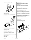
To Adjust Water Column Pressure (natural gas only, L.P. gas
must be regulated at source):
Remove the slotted vent cap on the top of the valve.
Turn the slotted adjustment screw, located on the top of the
valve next to the terminals clockwise to increase manifold
pressure and counterclockwise to decrease.
NOTE: If correct water column pressure cannot be
achieved, problem may be due to an undersized gas
supply line, a faulty or underrated gas meter, etc.
▲ WARNING
!
Test all connections for leaks by brushing on a
soapy water solution.
Never test for leaks with a flame!!!