


16 American Dryer Corporation 450431-3
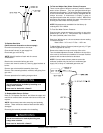
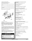
Tighten the two bolts under the drive shaft clockwise to raise
the tumbler and counterclockwise to lower the tumbler. The
bolts should be tightened in even increments in order to
ensure that the shaft runs parallel with the base of the dryer.
IMPORTANT: Side to side adjustment of the tumbler
should be equal on either side of the front panel, but
vertically the top of the tumbler should have a larger gap
than the bottom to compensate for the load.
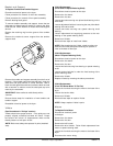
Be sure to tighten the left idler side to the same height as
the right side/drive side. This length can be determined by
taking measurements from the bottom of each pillow block
bearing to the top of the bearing pad.
NOTE: If the axle height is not the same on the drive and
idler side, then the tumbler will be either more to the right
or left side, depending on which axle is higher.
Tighten locking nuts on the adjustment bolts.
Reverse the first five steps for reassembly.
Check tumbler drive belt for proper tension. Adjust if
necessary.
Reestablish electrical power to the dryer.
Bearings
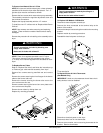
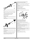
To Replace Drive/Idler Shaft Pillow Block Bearings
Discontinue electrical power to the dryer.
Remove the lint drawer.
Remove the lint door.
Loosen and roll V-belts off that connect speed reducing shaft
to drive shaft.
Place a piece of wood between the tumbler and wrapper to
support the tumbler when shaft is removed.
Remove the four bolts holding the drive shaft assembly in
the dryer.
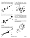
Remove cap screws from bushing of drive wheel.
Insert cap screws in tapped removal holes and tighten evenly
until bushing becomes loose on shaft.
Remove bushing and key.
Remove wheel from shaft.
Loosen the four setscrews in the pillow block bearings.
IMPORTANT: Tighten screws evenly and progressively.
Never allow the sheave to be drawn in contact with the
flange of the bushing. This gap should measure from 1/8”
to 1/4”. Proper cap screw torque is 30 ft.-lb. If greater
tightening forces are applied, excess pressures will be
created in the hub of the mounted sheave, which may
cause it to crack.
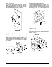
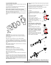
To Replace Motor Pulley
Discontinue electrical power to the dryer.
Remove the lint drawer.
Remove the lint door.
Loosen V-belts, then rotate pulley and roll V-belts out of its’
grooves.
Remove cap screws from bushing.
Insert cap screws in tapped removal holes and tighten evenly
until bushing becomes loose on shaft. Refer to figure “A”
on the previous page.
Remove bushing, pulley, and key.
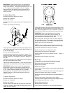
Assemble bushing and sheave as shown in figure “B” on
the previous page. When cap screws are loosely inserted,
bushing remains fully expanded to provide a sliding fit on
the shaft.
Insert key on the shaft, then slide sheave to desired position
with cap screw heads to the outside.
Tighten cap screws progressively. There should remain a
gap between the sheave hub and the flange of the bushing.
IMPORTANT: Tighten screws evenly and progressively.
Never allow the sheave to be drawn in contact with the
flange of the bushing. This gap should measure from 1/8”
to 1/4”. Proper cap screw torque is 6 ft.-lb., if greater
tightening forces are applied, excess pressures will be
created in the hub of the mounted sheave, which may
cause it to crack.
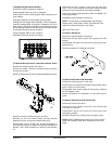
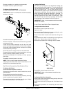
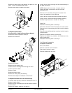
Tumbler Alignment
Discontinue electrical power to the dryer.
Remove the lint drawer.
Remove the lint door.
Remove both the left hand and right hand lint coop walls.
Loosen the V-belts on drive shaft, then rotate pulley and roll
V-belts out of its’ grooves.