


450431-3 www.amdry.com 15
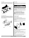
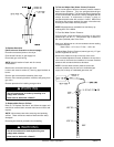
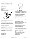
To Install New Main Door Glass
Remove main door assembly from dryer (follow main door
removal procedure).
Lay main door on flat surface with front of door face up.
Remove the four #10-32 Acorn nuts.
Remove glass and clean all old sealant off main door. This
area must be completely cleaned for correct bonding.
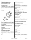
Apply a narrow bead of silicone (ADC P/N 170730) all around
main door area where glass will rest.
Install glass onto door/adhesive and slightly press glass in
place.
IMPORTANT: Do not press hard or silicone thickness
between the glass and door will be reduced, resulting in
poor bonding.
Secure the four #10-32 Acorn nuts to hold the glass.
The door assembly should now be put in an area where it
will not be disturbed for at least 24 hours. Depending on
the conditions, the curing time of this adhesive is 24 to 36
hours.
After 24-hour curing period, install main door on dryer by
reversing the first step.
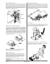
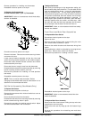
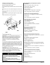
To Replace Front Panel
Discontinue electrical power to the dryer.
Remove main door switch and bracket assembly.
Follow procedure for removal of main door assembly.
Open control (service) door.
Remove lint drawer and open lint door by removing six
screws.
Unplug the door switch wires at the bottom of the front panel.
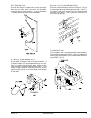
Disconnect the wires connecting the “EMERGENCY STOP”
(E-Stop). The easiest place to do this would be in the left
hand electrical box. Once the wires are disconnected, push
them through the inner top.
Remove the twelve Phillips head screws securing front panel
to dryer.
Pull wires up through front panel door switch wire channel
and gently remove front panel assembly.
Reverse this procedure for installing new front panel.
Reestablish electrical power to the dryer.
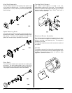
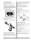
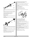
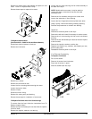
Pulleys
To Replace Drive Shaft Pulleys
Discontinue electrical power to the
dryer.
Remove the lint drawer.
Remove the lint door.
Remove right lint coop wall.
Loosen V-belts, then rotate pulley and
roll V-belts out of its’ grooves.
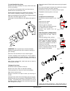
Remove cap screws from the
bushings.
Insert cap screws in tapped removal
holes and tighten evenly until bushing
becomes loose on shaft. Refer to
figure “A.”
Remove bushing, pulley, and key.
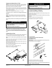
Assemble bushing and sheave as
shown in figure “B”. When cap screws
are loosely inserted, bushing
remains fully expanded to provide a
sliding fit on the shaft.
Insert key on the shaft, then slide
sheave to desired position with cap
screw heads to the outside.
Tighten cap screws progressively. There should remain a
gap between the sheave hub and the flange of the bushing.