


8 printed in U.S.A.
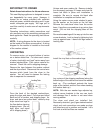
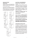
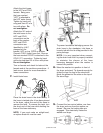
36 inch standpipe recommended
If standpipe is less than 36 inches (or floor
drain) – drain hose should be routed through the
clip to raise hose to the proper height, use clip
tie to securely hold drain hose in clip.
Installation accessory kits are available for other
types of drain facility conditions…see Washer
Installation Accessory Kits table on page 13.
The use of a laundry built-in wall box can greatly
simplify installation.
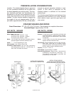
If the faucets and/or drain is located to either
side of the stacked washer/dryer, openings are
located in the dryer stand uprights to allow
hoses and power cords to be passed through.
This is to allow installation against the back wall.
(This is dependent on venting used.)
GAS CONNECTION
Gas operated dryers are equipped with a burner
orifice for operation on NATURAL GAS. If the
dryer is to be operated on LP GAS, it must be
converted correctly for safety and proper
performance. Conversion kits from NATURAL to
LPG, or LPG to NATURAL are available through
your local Maytag dealer. If other conversions
are required, check with local gas utility for
specific information concerning conversion
requirement. NOTE: The conversion should
always be performed by a qualified service
technician.
NOTE: If the dryer is to be converted in
Canada, the conversion shall be carried out in
accordance with the requirements of the
provincial authorities having jurisdiction and in
accordance with the requirements of the CAN-
B149.1 and CAN1-B149.2 installation code.
A 1/2 inch gas supply line is recommended and
must be reduced to connect to the 3/8 inch gas
line on the dryer.
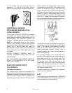
IMPORTANT NOTE: When installing the gas
line, route it so that it will not interfere with the
washer once the washer is pushed back into
position. It is important to make sure the gas line
does not come into contact with either the
washer drain hose or any part of the washer.
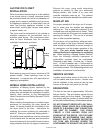
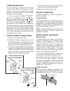
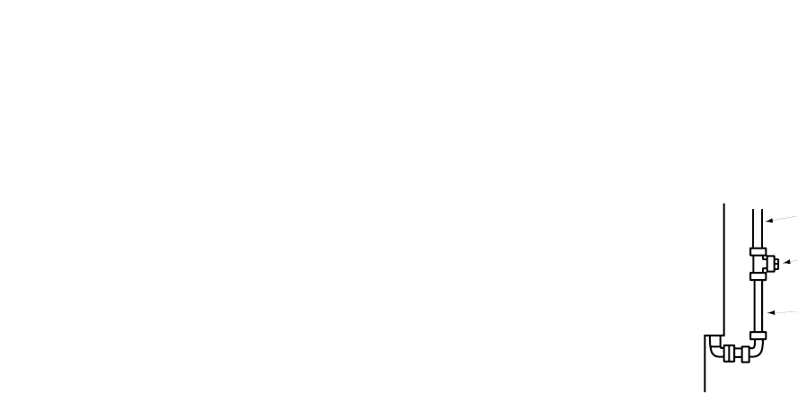
NOTE: A 3/8 inch x 1 inch pipe nipple is includ-
ed to adapt valve connection from a 3/8 inch
female to a 3/8 inch male I.P.S. connection.
Additionally, a 1/8 inch N.P.T. (National Pipe
Thread) plugged tapping, accessible for test
gauge connection, must be installed immediately
upstream of the gas supply connection to the
dryer.
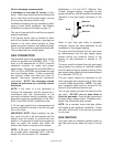
Dryer
Gas Line
1/8" NPT Plug
Gas Line
Refer to your local gas utility or plumbing
contractor should you have questions on the
installation of the plugged tapping.
The dryer and its individual shut-off valve must
be disconnected from the gas supply piping
system during any pressure testing of the
system at test pressures in excess of 1/2
P.S.I.G.
The dryer must be isolated from the gas supply
piping system by closing its individual manual
shut-off valve during any pressure testing of the
gas supply piping system at test pressures equal
to or less than 1/2 P.S.I.G.
The gas supply should be connected to the
dryer using pipe joint compound or a Teflon tape
on male thread connections. NOTE: Any pipe
joint compound used must be resistant to the
action of any liquefied petroleum gas.
Turn on gas supply and open the shut-off at the
gas valve. DO NOT use an open flame to
check for gas leaks. Check all gas connections
for leaks using a soap solution. If bubbles occur,
tighten the connections and recheck.
NOTE: As a courtesy, many local gas utilities
will inspect a gas appliance installation. Check
with your utility to see if this service is provided
in your area.
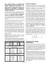
GAS IGNITION
This dryer uses an automatic ignition system to
light the main burner when the dryer is turned
on.