


9
Electrical Connection
1. Turn off power at fuse box or breaker box.
2. Open top of washer with key. Prop the top open with
the support.
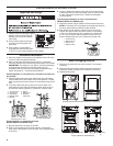
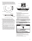
3. Remove approximately 6" (150 mm) of shielding from cable
end to expose insulated wires. Be sure that there is sufcient
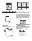
wire to create a drip loop or wire sag, as shown.
4. Strip wire insulation an adequate
length to make connections. Install
eyelets on ground wires with a
crimping tool.
5. Remove locking nut from strain relief provided with washer.
Thread wire through strain relief and thread wire through
hole in back of the washer until strain relief penetrates hole.
Route strain relief nut around wires and tighten nut onto
strain relief body.
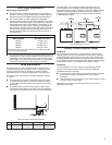
6. Connect two or three current conducting wires into the
connector and tighten the screw connectors; single phase
and three-phase connections are shown in the illustrations.
Attach ground to the frame ground bolt as shown in the
illustrations and tighten the locking nut.
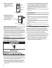
British standard
pipe thread
tting
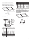
Water Supply Connection
Connect the water supply to the washer using the exible inlet
hoses provided. Do not use a rigid connection for the water
supply.
NOTE: The water connection to the washer
requires a 3⁄4" British Standard Pipe Thread
tting. The ground end is a U.S. thread.Threading
an NPT tting or the NPT end of the inlet hose
will damage the threads of the ll valve.
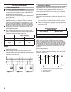
1. Flush water lines to remove debris. Install the
rubber washers in both tting ends of each inlet
hose. Install the non-grooved tting nut of the inlet
hoses to the hot and cold inlet valves. Tighten
ttings.
2. Attach grooved end of the inlet
hoses to the washer. Tighten ttings.
3. Turn on water and check for leaks
in the system.
Drain Connection
1. Cut the pre-formed drain hose so it ts properly on the drain
or in the drain channel.
2. Attach drain hose to washer with clamp provided. If tted
directly to a drain pipe, use a clamp on the drain pipe as well.
Laundry Product Supply Pump Connection
Up to 8 laundry product supply pumps may be connected to the
washer. Tubing and relay connections are provided in the back
of the washer.
NOTE: Route hoses and wiring so they will not be pinched,
damaged, or rubbed during use.
Electrical Relay Connection
The electrical connections are relay connections only and do
not provide adequate power for the pumps. The laundry product
supply pump(s) must be powered by a separate electrical source.
PN Models
1. Turn off power at circuit breaker or fuse box.
2. Remove panel screw and remove cover. Connect relay leads
to numbers 1 through 8. Connect common/ground to lead 10.
3. Replace cover.
PD Models
1. Turn off power at circuit breaker or fuse box.
2. Open top cover. Route control wires through washer and
to relay connector on control panel. Connect leads.
NOTE: Support control wires with wire ties to keep them
away from moving parts.
3. Replace cover.
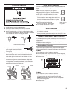
A drip loop or wire sag keeps
condensation from running
into washer
3-phase connection
Single-phase connection
NPT tting
Ground
Ground
L1 L2 L3
L1 L2