


5
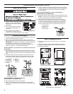
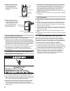
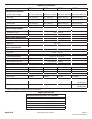
MFS18 MFS25 MFS35 MFS55
X4 3.81"
(97 mm)
3.42"
(87 mm)
1.97"
(50 mm)
1.06"
(27 mm)
X5
(min.)
4.53"
(115 mm)
4.53"
(115 mm)
5.32"
(135 mm)
4.76"
(121 mm)
X6 5.12"
(130 mm)
5.12"
(130 mm)
3.15"
(80 mm)
1.55"
(39.5 mm)
X7 2.76"
(70 mm)
2.76"
(70 mm)
1.77"
(45 mm)
6.69"
(170 mm)
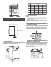
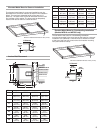
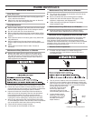
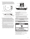
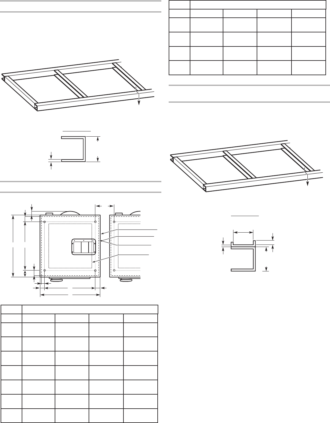
Elevated Metal Base for Freestanding Installation
(Models MFS18 and MFS25 only)
The elevated metal base for a freestanding installation
must be constructed in the same way as the base for a secured
installation. An additional U channel must be welded or bolted
to the top of the front rail to secure the front washer mounting
feet (see illustration below).
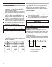
Elevated Metal Base for Secured Installation
The elevated metal base for a secured installation may be
fabricated from a metal U-channel as shown in the illustration
below. The maximum allowable height of the base is 12"
(300 mm). The base must be able to withstand both the load
and vibration of the washer. The base must be adequately
secured with anchor bolts or cement anchors.
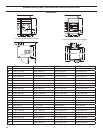
0.160"
(4 mm)
min.
12"
(300 mm)
max.
A
U-Channel
B
U-Channel
12"
(300 mm)
max.
0.63"
(15 mm)
2.38"
(60 mm)
0.19"
(5 mm)
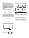
Dim. Model
A
B
MFS18 MFS25 MFS35 MFS55
A 25.99"
(660 mm)
25.99"
(660 mm)
32.67"
(830 mm)
35.46"
(901 mm)
B 28.15"
(715 mm)
32.48"
(825 mm)
38.39"
(975 mm)
36.40"
(925 mm)
C 17.91"
(455 mm)
22.24"
(565 mm)
32.09"
(815 mm)
33.30"
(846 mm)
D 22.05"
(560 mm)
22.05"
(560 mm)
28.15"
(715 mm)
31.50"
(800 mm)
X1 1.14"
(29 mm)
1.14"
(29 mm)
1.18"
(30 mm)
1.77"
(45 mm)
X2 3.46"
(88 mm)
3.46"
(88 mm)
1.97"
(50 mm)
1.06"
(27 mm)
X3 1.97"
(50 mm)
1.97"
(50 mm)
2.26"
(57.5 mm)
1.98"
(50.5 mm)
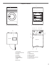
X5
A
D
X3
X3
BC
X2
X1
X6
X4
X7
Outline of frame
Outline of riser
Outline of cabinet
Inside of riser
Dim. Model
Anchor Bolt Placement
Minimum material thickness 0.160" (4 mm)
Minimum material thickness 0.160" (4 mm)