


10
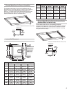
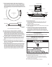
Tubing Connectors
All models
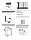
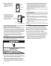
There are 6 tubing connectors in back of the washer. One
connector is larger in diameter than the others. The larger
diameter connector should be used for the pump requiring
chemical mixing with water prior to entering the washer. If
additional chemicals are needed, contact the manufacturer.
Tubing connectors are sealed at the factory and must be drilled
out before use.
NOTES:
■ Only drill out connectors that will be used. Any unused
open connectors must be sealed to avoid reux during
the ll cycle.
■ Holes must be drilled. Attempting to open holes with a punch
may damage the washer.
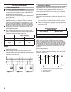
1. Drill out connectors that will be used. Use a drill bit slightly
smaller than the interior diameter of the hole. Small tubes are
11/32" and larger tube is 13/32". Remove all debris from the
hole. See illustration.
2. Attach exible hoses rated for commercial laundry chemicals
to the connectors. (Secure hoses with hose clamps.)
PD models only
These additional steps are necessary to connect tubing
connectors:
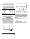
3. Open top cover. Locate
connectors that were drilled.
Attach tightly tting exible
hoses rated for commercial
laundry chemicals onto those
connectors on the inside of the
washer, long enough to reach
the dispenser box connectors.
Secure each hose with
a hose clamp.
4. Be sure that dispenser connectors t the hoses. Drill out
connectors on the dispenser box with a drill bit slightly
smaller than the interior diameter of the hole. Small tubes
are 11/32" and larger tube is 13/32". Remove all debris
from the hole.
5. Attach exible hoses rated for commercial laundry chemicals
to the connectors. Secure the hoses with a hose clamp.
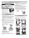
Complete Installation
1. Turn off power at fuse box or breaker box.
2. Be sure that the shipping brackets are removed.
3. Open door and be sure that the washer drum is empty.
4. Verify that washer is level and does not rock from
side-to-side.
5. Check electrical connection and ground.
6. Turn on water.
7. Adjust vibration switch. See “Vibration Switch Adjustment”
in Maintenance.
8. Check drain connection and clearance.
9. Turn power on at circuit breaker.
10. Turn the washer on. Begin a wash cycle. Watch the drum
during the extraction cycle. The drum should rotate
clockwise as observed from the front of the washer.
11. Make sure all panels are installed.
IMPORTANT: If the drum rotates counter-clockwise in extract
mode, turn off the power supply at the circuit breaker and reverse
the polarity of any 2 of the supply wires from the frequency
inverter to the motor, or on the motor itself. This should only be
performed by qualied personnel.
11. Perform vibration switch function test (see page 11 “Vibration
Switch Adjustment and Function Test”).
12. Begin wash cycle again. Activate the emergency stop switch.
All electrical power to the washer should be deactivated.
Break-In Period
The following checks and adjustments should be performed
during the break-in period as follows:
24 operation hours
■ Check belt tightness. See page 12, “Belt Inspection and
Adjustment”.
80 operation hours
■ Check belt tightness. See page 12, “Belt Inspection and
Adjustment”.
■ Check mounting bolt tightness. Retighten if necessary
(secured installation only).
Controls Troubleshooting
For programming and controls troubleshooting, refer to the
Programming Guide.
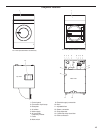
Dispenser connectors –
Rear view