


of the fans are constant speed and are cycled separately using
ambient sensing thermostats.
Flooded Head Pressure Control Valve (FHP)
The FHP system of head pressure control is a completely
automatic control that maintains a preset condenser pressure
without need of seasonal adjustment. The control maintains
head pressure by backing liquid into the leaving side of the
condenser, decreasing the effective condenser surface and
therefore maintaining a constant head pressure upon a drop
in ambient temperature.
Several styles of flooding valves or combinations of valves
are available. Contact the valve manufacturer for specific
recommendations.
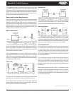
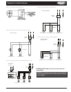
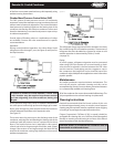
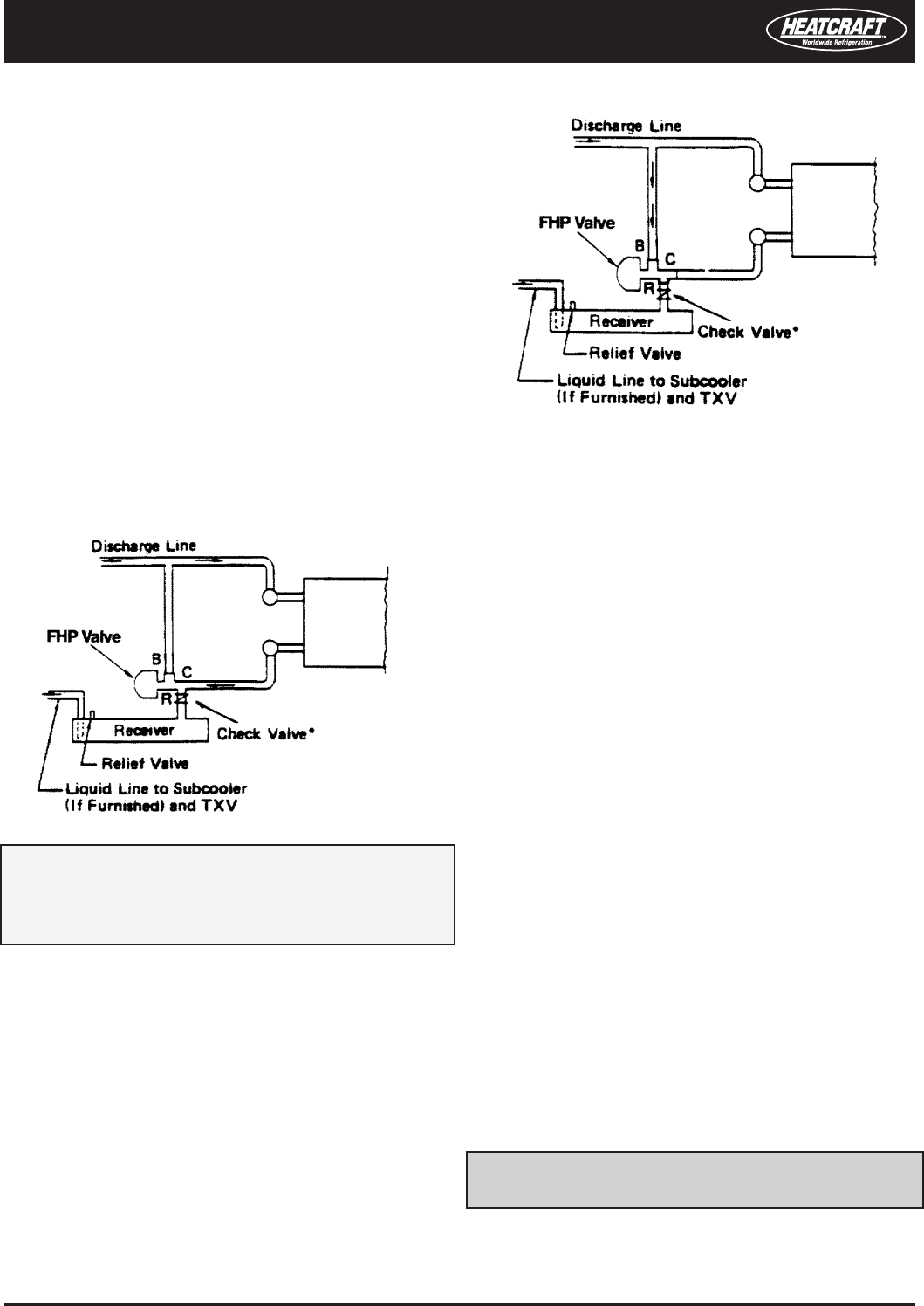
Operation:
During normal ambient operation, the valve allows liquid
refrigerant to ow through C port (see Figure 9) and R port to
the liquid receiver.
As the pressure drops with a drop in ambient temperature,
the valve opens to allow high pressure discharge gas to enter
B port, pass through the valve and pressurize the receiver to
provide adequate liquid ow to the expansion valve.
(see Figure 10)
This action raises the pressure on the discharge side of the
condenser, reducing ow and ooding the leaving side of the
condenser until the pressure rises to a proper level to close
B port. The liquid receiver size is important in this type of
control and must be large enough to hold the total system
charge. If the receiver is not large enough, the liquid will be
stored in the condenser causing high head pressure at normal
ambient temperatures.
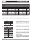
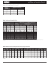
The refrigerant charge required will often be about two times
the normal charge for cold weather operation. The amount of
refrigerant that must be added to a system for winter or cold
weather operation is determined by Tables 6, 7 and 8.
(see page 10)
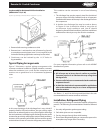
Piping:
As on all systems, refrigerant migration must be prevented
when using FHP. If the receiver is in a warm location, a check
valve should be placed in the line between the FHP valve
and the receiver. Good piping practice suggests a trap in
the compressor discharge line and an inverted trap at the
condenser outlet. Multiple valve applications must have valves
piped in parallel.
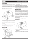
Maintenance
Air-cooled condensers require minimum maintenance. The
unit coil will require a periodic cleaning and this can be
accomplished by a brush, vacuum cleaner, pressurized irstream
or a commercially available coil cleaning foam.
All of the condenser fan motors have sealed ball bearings. The
only acceptable service to these bearings is replacement.
Cleaning Instructions
Heatcraft recommends that the finned surface of this unit
be cleaned approximately every six months; more frequent
cleaning may be required if extreme conditions cause clogging
or fouling of air passages through the nned surface.
Calgon Corporation’s CalClean 41352 (or equal) should be
acceptable for cleaning this unit. CalClean should be applied
liberally to entering air and leaving air surfaces of the nned
area in accordance with the label directions.
CAUTION: Under no circumstances should this unit be
cleaned with an acid-based cleaner�
*If receiver is located in a warm ambient, a check valve
in this location may be required to prevent receiver
gas from migrating into the condenser during the
o cycle�
Remote Air-Cooled Condenser Installation and Operations Manual, August 2007 9
Remote Air-Cooled Condenser
Figure 9.
Figure 10.