


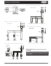
Electrical Wiring
The electrical installation should be in accordance with
National Electrical Code, local codes and regulations. Proper
overcurrent protection should be provided for the fan motors.
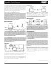
Wiring diagrams shown are only basic and do not show
fuses, disconnect switches, etc., which must be provided in
the eld.
All standard motors have internal inherent overload protectors.
Contactors can be used instead of starters requiring thermal
protectors, eliminating the problem of furnishing the proper
heating elements.
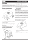
All air-cooled condensers are furnished with either single-
phase or three-phase fan motors, identied by the unit data
plate. Three-phase motors must be connected to three-phase
power voltage to agree with motor and unit data plate.
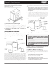
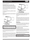
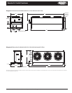
The motors must be checked for proper rotation. Be sure
to check that motor voltage and control connection agree
with electric services furnished. The motors are wired into
a common junction box. Where fan cycling is furnished and
factory installed, the motors are completely wired through the
control and to the contactors.
Electrical leads from each motor terminate at the unit junction
box. Field connections must be made from these leads through
a contactor, fuse and disconnect in accordance with local, state
and national codes.
6 Part # 2500018
Installation and Operations Manual
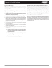
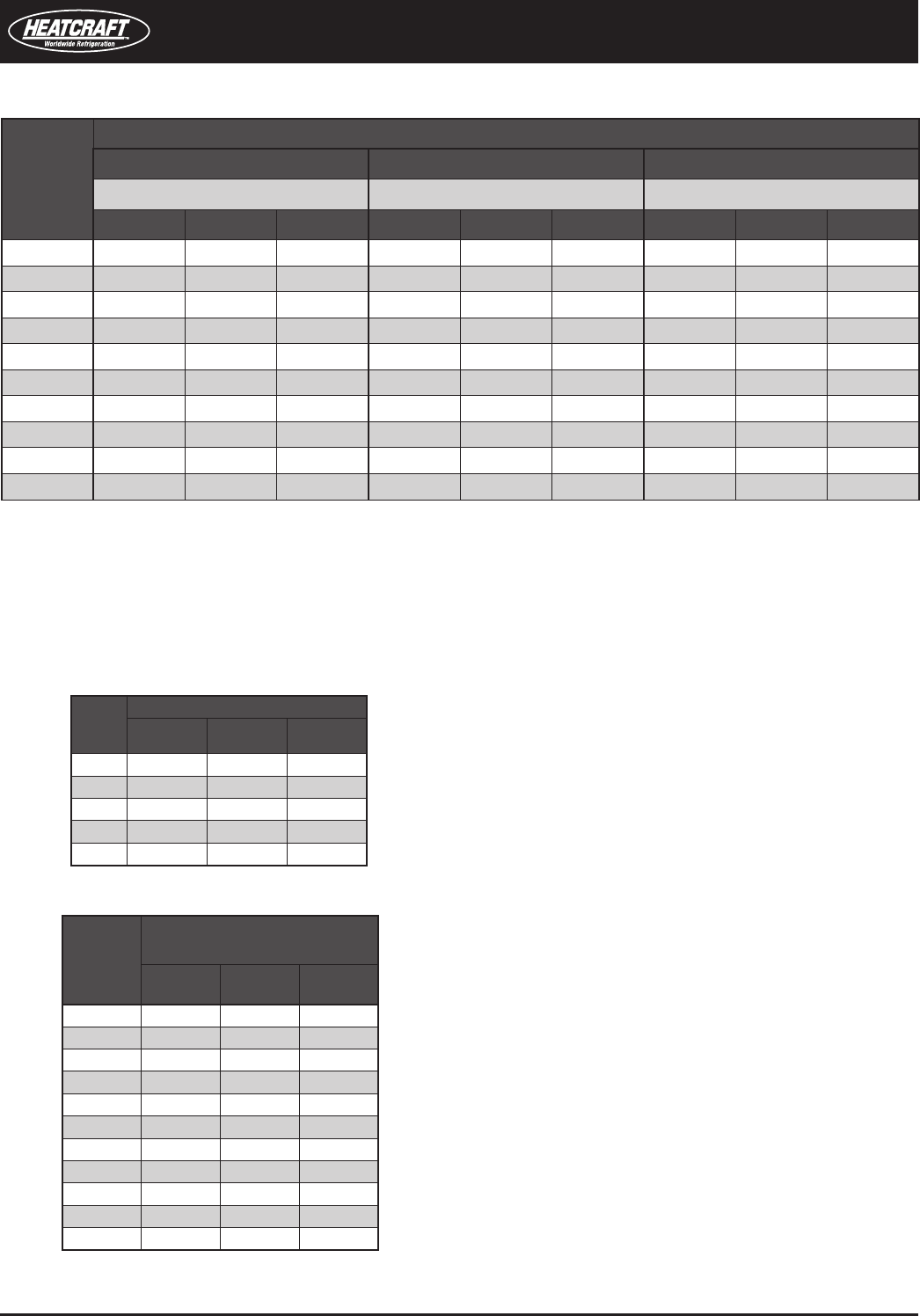
Line Size
(Type L
Copper
OD)
Drain Line
Velocity 100 FPM Refrigerant
R-22
R-404A/
R-507
R-410A
1/2 2.30 1.50 2.00
5/8 3.70 2.30 3.20
7/8 7.80 4.90 6.70
1-1/8 13.20 8.30 11.40
1-3/8 20.20 12.60 17.40
1-5/8 28.50 17.90 24.60
2-1/8 49.60 31.10 42.60
2-5/8 76.50 48.00 66.00
3-1/8 109.20 68.40 94.20
3-5/8 147.80 92.60 127.40
4-1/8 192.10 120.30 165.70
Temp.
Discharge Line
R-22
R-404A/
R-507
R-410A
90 0.88 0.92 0.89
100 0.95 0.97 0.96
110 1.04 1.01 1.03
120 1.10 1.03 1.10
130 1.18 1.04 1.16
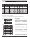
Table 3� Tons of Refrigeration, Drain
Table 2� Condensing Temperature Correction Factor
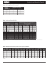
Line Size
(Type L
Copper OD)
Discharge Line
R-22 R-404A/R-507 R-410A
Sat. Suction Temp (°F) Sat. Suction Temp (°F) Sat. Suction Temp (°F)
-40 0 40 -40 0 40 -40 0 40
1/2 0.75 0.80 0.85 0.61 0.70 0.79 1.17 1.26 1.33
5/8 1.40 1.50 1.60 1.14 1.31 1.48 2.20 2.36 2.49
7/8 3.70 4.00 4.20 2.98 3.44 3.87 5.76 6.12 6.52
1-1/8 7.50 8.00 8.50 6.01 6.96 7.81 11.64 12.50 13.17
1-3/8 13.10 14.00 14.80 10.46 12.10 13.58 20.21 21.72 22.88
1-5/8 20.70 22.00 23.40 16.49 19.07 21.41 31.92 34.30 36.14
2-1/8 42.80 45.70 48.50 34.08 39.43 44.26 65.88 70.78 74.57
2-5/8 75.40 80.40 85.40 59.95 69.36 77.85 115.90 124.53 131.20
3-1/8 120.20 128.20 136.20 95.48 110.47 124.00 184.62 198.36 208.98
3-5/8 178.40 190.30 202.10 141.46 163.67 183.71 273.54 293.90 309.69
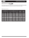
Table 1� Tons of Refrigeration, Discharge
Source: ASHRAE Refrigeration Handbook.
Line sizes based on pressure drop equivalent to 1°F per 100 equivalent feet.
Values in table are based on 105°F condensing temperature. Multiply table capacities by the factors in Table 2 for other condensing temperatures.
If subcooling is substantial or the line is short, a smaller line size may be used. Applications with very little subcooling or very long lines may require
larger sizes.
1.
2.
3.
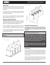
Tables 1, 2 and 3 provide recommendations for discharge and liquid drain line sizes for
remote condenser selections.