


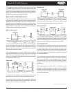
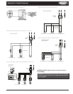

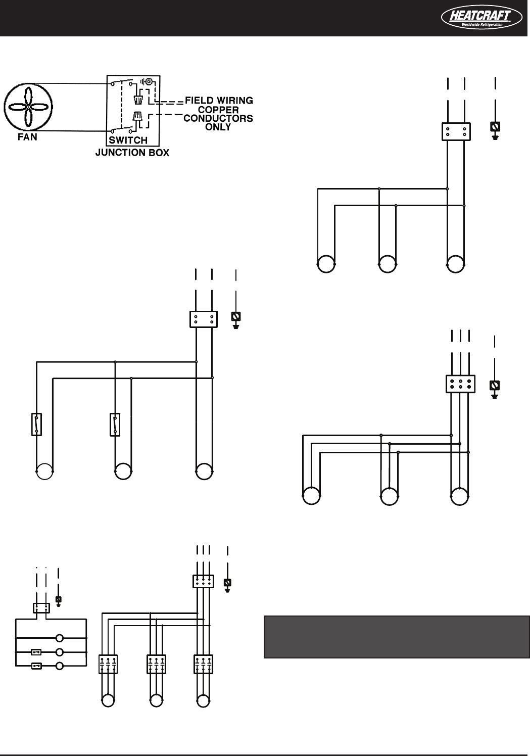
Diagram 3. Typical Wiring Diagram for 208-230/1/60 with Fan Cycling.
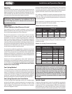
Diagram 5. Typical Wiring Diagram for 208-230-460/3/60 with Fan Cycling
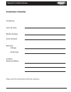
Diagram 4. Typical Wiring Diagram for 208-230-460/3/60
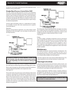
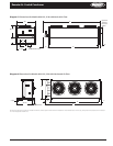
Diagram 1. Typical Wiring Diagram for Models 1-3.
CONTROL CIRCUIT: May be 24 volt, 120 volt, or 230 volt
(as specied)�
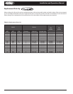
Diagram 2. Typical Wiring Diagram for 208-230/1/60
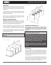
WARNING: There may be more than one source of electrical
current in this unit� Do not service before disconnecting all
power supplies�
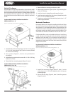
Remote Air-Cooled Condenser Installation and Operations Manual, August 2007 7
Remote Air-Cooled Condenser
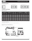
Models 049-080; 10-16
Models 008-040; 1-8
Models 105-133; 21-26
TERMINAL
BOARD
T3T2T1
208-230V/3 phase/60Hz
M1M2
M3
FAN MOTORS
460V/3 phase/60Hz
TERMINAL
BOARD
T2
208-230V/1phase/60Hz
T1
M1
M2
FCC
M3
FCC
Models 049-080; 10-16
FAN MOTORS
Models 105-133; 21-26
TERMINAL
BOARD
T2
208-230V/1phase/60 Hz
T1
M1
M2
M3
FAN MOTORS
Models 049-080; 10-16
Models 008-040; 1-8
Models 105-133; 21-26
TERMINAL
BOARD
T3T2T1
208-230V/3 phase/60Hz
GND
T2
BOARD
TERMINAL
T1
M1
C1
C1
M2
C2
FCC
COM NC
C2
M3
C3
FCC
COM NC
C3
FAN MOTORS
CONTACTOR COILS
THERMOSTATS OR
PRESSURE CONTROLS
CONTACTORS
CONTROL CIRCUIT*
Models 049-080; 10-16Models 105-133; 21-26
460V/3 phase/60Hz