


Vertical Condenser
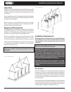
Vertical airow units should be located no closer than the width
of the unit from a wall or other obstruction. If two or more units
are to be positioned in the same area, a similar distance should
be maintained between adjacent units. Sufficient free area
should be left around and below unit to avoid air restriction
to coil.
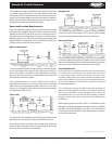
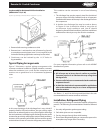
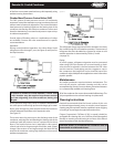
Leg Assembly for Vertical Airow Installation
(Models 008-016; 1-3)
Assemble the unit’s two legs (Figure 3, item 2) using three
1/4 - 20 x 3/4” long bolts per leg. Captive nuts are provided
on unit for this assembly.
Four gussets (Figure 3, item 3) are provided for
leg support.
Assemble the gusset in each corner with 1/4 - 20 x 3/4” long
bolts and 1/4” nuts.
Discard the four mounting angles (Figure 5, item 1).
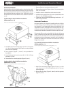
Leg Assembly for Vertical Airow Installation
(Models 024-133; 5-26)
1.
2.
3.
4.
Remove fasteners securing condenser to skid.
Remove leg extensions (Figure 4, item 1) by removing four
5/16” x 3-1/2” bolts.
Install as shown in dotted lines with same four bolts.
Install mounting angle (item 2) as shown (dotted lines) with
four 1/4 - 20 x 3/4” bolts provided.
Condenser can be hoisted by attaching hooks into 1-1/2”
holes in leg assemblies.
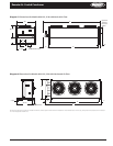
Horizontal Condenser
Horizontal airow units should be installed with the coil (inlet
air side) facing the prevailing winds. Where strong winds
are common, it is recommended that a wind deflector (not
supplied) be used to discharge the air vertically from the unit,
to prevent capacity loss during varying wind conditions. The
wind deector should be installed on the fan side of the unit.
If horizontal airow units are installed with the air inlet facing
a wall, a distance of at least 48 inches should be maintained
between unit and wall. If it is necessary to have the unit
positioned so the air discharge is toward a wall, it should be
spaced at a distance no less than three times the coil face
height from the wall.
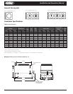
Leg Assembly for Horizontal Airow Installation
(Models 008-016; 1-3)
Attach four mounting angles (Figure 5, item 1) to the
unit, using two 1/4 - 20 x 3/4” long bolts and 1/4” nuts per
mounting angle.
Discard the two legs, (Figure 3, item 2) and four gussets
(Figure 3, item 3).
1.
2.
3.
4.
5.
1.
2.
4 Part # 2500018
Installation and Operations Manual
Figure 5. Leg assembly (horizontal airow, models 008-016 ; 1-3)
Figure 4. Leg assembly (vertical airow, models 024-133; 5-26)
Figure 3. Leg assembly (vertical airow, models 008-016; 1-3)