


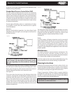


Start Up
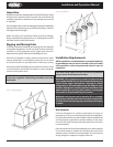
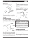
Check for proper fan rotation. Air is drawn through the coil on
all units. Be sure the fans turn freely. Rotation of the motors and
blades should be in a clockwise direction looking at the unit
from the blade side. On three-phase units, it may be necessary
to reverse two of the three power leads to the unit.
NOTE: The manifold assembly is not designed to support
field piping� Any damages to the condenser due to
excessive weight, pressure or vibration will not be covered
by standard warranty�
Operation
Winter Operation Head Pressure Control
The capacity of an air-cooled condenser varies with the
dierence between the entering air dry bulb temperature and
the condensing temperature of the refrigerant.
Because air temperature in some regions varies as much as
100 degrees from summer to winter, some means must be
employed to keep the condensing temperature suciently
high to ensure proper operation of the refrigerant expansion
valve during low ambient operation, and also allow sucient
capacity so that excessively high condensing temperatures do
not result during high ambient conditions. The low limit of the
head pressure is dependent upon the required pressure drop
across the thermostatic expansion valve.
For normal air conditioning applications, head pressure should
be maintained above a condensing temperature corresponding
to 90°F. This corresponds to a normal lower limit of about 60°F
ambient air. Because air conditioning is not normally required
at these lower ambient temperatures, condenser head pressure
control may not always be necessary.
However, for those applications below 60°F ambient air
temperature, two methods of condenser head pressure control
are available to meet specic job requirements and engineer/
owner preference: Fan Cycling, Variable Speed and Flooded
Head Pressure Control (FHP)�
Fan Cycling Method
This is an automatic winter control method and will maintain
a condensing pressure within reasonable limits by cycling fan
motors in response to outside air temperature entering the
condensing coil. When voltage other than 230/208 is supplied
to the unit, a transformer will be provided for eld installation.
Electrical protection must be provided for this transformer.
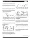
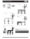
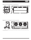
Fan Cycling Operation and Installation
The fan cycling control package consists of a weather-tight
enclosure with motor starting contactor(s), as required, and
thermostat(s). The contactor coil is 24 volts, 115 volts or 240
volts as ordered. The thermostats and contactors are wired as
shown on Diagrams 3 and 5.
Factory-installed packages are mounted on the unit and have
all motor connections completed. Field wiring consists of
connecting this panel to a power supply and fused disconnect(s)
together with the control circuit to the contactor coils.
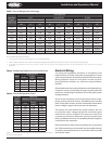
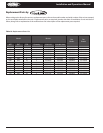
Fan cycling is suitable for outside temperatures above those
shown in Table 4. The thermostat should be eld set to shut
o the fan when the condensing temperature is reduced to
approximately 90°F.
Where operation at ambients below the range shown on
Table 4 were required, FHP must be added.
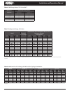
Table 5 lists approximate settings for several system T.D.’s. These
settings are approximate as they do not take into account
variations in load.
NOTE: Fans closest to the headers should not be cycled
on standard temperature or pressure controls� Dramatic
temperature and pressure changes at the headers as a
result of fan action can result in possible tube failure� Fan
motors are designed for continuous duty operation� Fan
cycling controls should be adjusted to maintain a minimum
of ve (5) minutes on and ve (5) minutes o� Short cycling
of fans may result in a premature failure of motor and/or
fan blade�
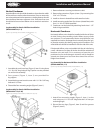
Variable Speed
Condenser head pressure control is provided by varying the
air ow through the condenser by changing the RPM of the
condenser fan. This control package is oered in combination
with ambient fan cycling. The fan motor next to the header
end of the condenser is the variable speed fan. The remainder
8 Part # 2500018
Installation and Operations Manual
Model
Design T.D.
30°F 25°F 20°F 15°F
2-fan units 45 55 65 70
3-fan units 30 40 50 60
Table 4� Minimum Ambient for Fan Cycling
Model Design T.D. (°F)
Thermostat Settings
T1 T2
2-fan units
30 55 -
25 60 -
20 65 -
3-fan units
30 60 45
25 65 50
20 75 55
15 75 65
Table 5� Fan Cycling Thermostat Settings