


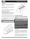
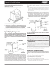
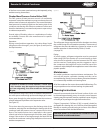
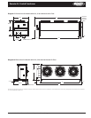

Leg Assembly for Horizontal Airow Installation
(Models 024-133; 5-26)
Remove bolts securing condenser to skid.
Remove item 1 and attach to rear of bottom leg (item A)
to complete mounting base. Item 2 is not required in the
horizontal discharge application and may be discarded.
Condenser can be hoisted by the 1-1/2” holes in
leg assemblies.
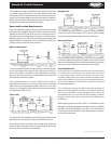
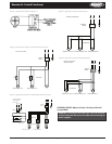
Typical Piping Arrangements
Figure 7 illustrates a typical piping arrangement with
a remote condenser located at a higher elevation, common
when the condenser is on a roof and the compressor and
receiver are on grade level or in a basement equipment
room.
In this case, the design of the discharge line is very critical. If
properly sized for full load conditions, the gas velocity might
be too low at reduced loads to carry oil through the discharge
line and condenser coil. Reducing the discharge line size would
increase the gas velocity suciently at reduced load conditions;
however, when operating at full load, the line would be greatly
undersized and create an excessive refrigerant pressure drop.
1.
2.
3.
This condition can be overcome in one of two following
ways:
The discharge line may be properly sized for the desired
pressure drop at full load conditions and an oil separator
installed at the bottom of the trap in the discharge line from
the compressor.
A double riser discharge line may be used as shown
in Figure 8. Line A should be sized to carry the oil
at minimum load conditions and Line B should
be sized so that at full load conditions, both lines would have
sucient ow velocity to carry the oil to the condenser.
For more complete information, please refer to the ASHRAE
Handbook on Systems.
NOTES:
All oil traps are to be as short in radius as possible�
Common practice is to fabricate the trap using three
90-degree ells�
Pressure relief valves are recommended at the condenser
to protect the coil�
A drain line check valve is recommended for applications
where the condenser may be at a lower temperature
than the receiver�
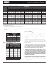
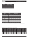
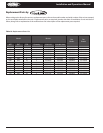
See Tables 1, 2, and 3 for discharge and liquid drain line size
recommendations for remote condenser selections.
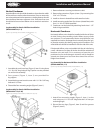
Installation, Refrigerant Piping
Install piping according to standard accepted refrigeration
practice. The following recommendations should be adhered
to:
Use only refrigeration-grade copper tubing.
Soft solder joints are not acceptable.
Put dry nitrogen through lines while brazing.
Do not leave dehydrated piping or components open to the
atmosphere any longer than is necessary.
1.
2.
1�
2�
3�
1.
2.
3.
4.
Remote Air-Cooled Condenser Installation and Operations Manual, August 2007 5
Remote Air-Cooled Condenser
Figure 6. Leg assembly (horizontal airow, models 024-133; 5-26)
Figure 7
Figure 8