


20
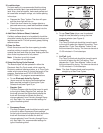
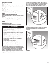
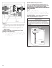
The connecting piece supplied with your WTA 3510
dryer must then be inserted in the vent opening that will
be used. See Figure 16.
Figure 16.
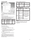
Checking/Installing Exhaust Ducting
The ducting system of the dryer, for optimum
performance, should be as short as possible with
a minimum number of elbows. Your WTA 3510 electric
vented dryer will work best when the venting system has
as few restrictions to the flow of air as possible.
Whether installing to an existing venting system or a new
venting system, make sure that all ducting is clean and
free of lint and does not exceed the length per elbows as
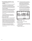
shown in Table 1, below:
Maximum length of duct
Number
of Elbows
Rigid Duct Flexible Duct
0
1
2
3
30 ft. (914 cm)
22 ft. (670 cm)
14 ft. (427 cm)
6 ft. (183 cm)
20 ft. (610 cm)
15 ft. (457 cm)
9 ft. (274 cm)
4 ft. (122 cm)
Table 1.
Every elbow must have a minimum diameter of 4 inches
(10 cm).
The above table assumes the use of an approved
exhaust vent hood with a swing out damper. DO NOT
use an exhaust vent hood with magnetic latches.
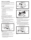
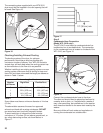
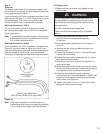
To avoid restriction of exhaust the outlet must be
a minimum of 12 inches (30 cm) above ground level, or
any other obstructing surface, as shown below, in
Figure 17.
12” (30 cm) min.
Figure 17.
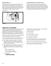
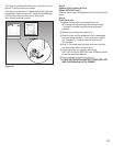
Step 5
Condensate Hose Connection
(Model WTL 5410 only!)
The WTL 5410 must have its condensate drain line
installed and run to a suitable drain. The connection
for the condensate hose is located on the back of the
WTL 5410, see Figure 18.
Figure 18.
Connect the condensate drain hose to the dryer.
The other end should then be placed and secured at
a nearby sink or drain, or if installed with a washer it
may, room permitting, be installed next to the washer
drain hose and drained to the same drain used by the
washer.
Be sure to follow all local codes and regulations in
running the condensate to a suitable drain.