


8 American Dryer Corp. 113610-1
!
!
!
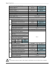
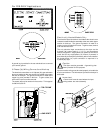
Fresh Air Supply Requirements ______
When the dryer is operating, it draws in room air, heats it,
passes this air through the tumbler, and exhausts it out of
the building. Therefore, the room air must be continually
replenished from the outdoors. If the make-up air is
inadequate, drying time and drying efficiency will be adversely
affected. Ignition problems and sail switch “fluttering”
problems may result, as well as premature motor failure
from overheating. The dryer must be installed with provisions
for adequate combustion and make-up air supply.
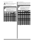
Air supply (make-up air) must be given careful consideration
to ensure proper performance of each dryer. As a general
rule, an unrestricted air entrance from the outdoors
(atmosphere) of a minimum of 150
2
inches (967.74
2
cm) is
required for each dryer. (Based on 1
2
inch per 1,000 Btu.)
To compensate for the use of registers or louvers used over
the openings, this area must be increased by approximately
thirty-three percent. Make-up air openings should not be
located in an area directly near where exhaust vents exit the
building.
It is not necessary to have a separate make-up air opening
for each dryer. Common make-up air openings are
acceptable. However, they must be set up in such a manner
that the make-up air is distributed equally to all the dryers.
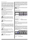
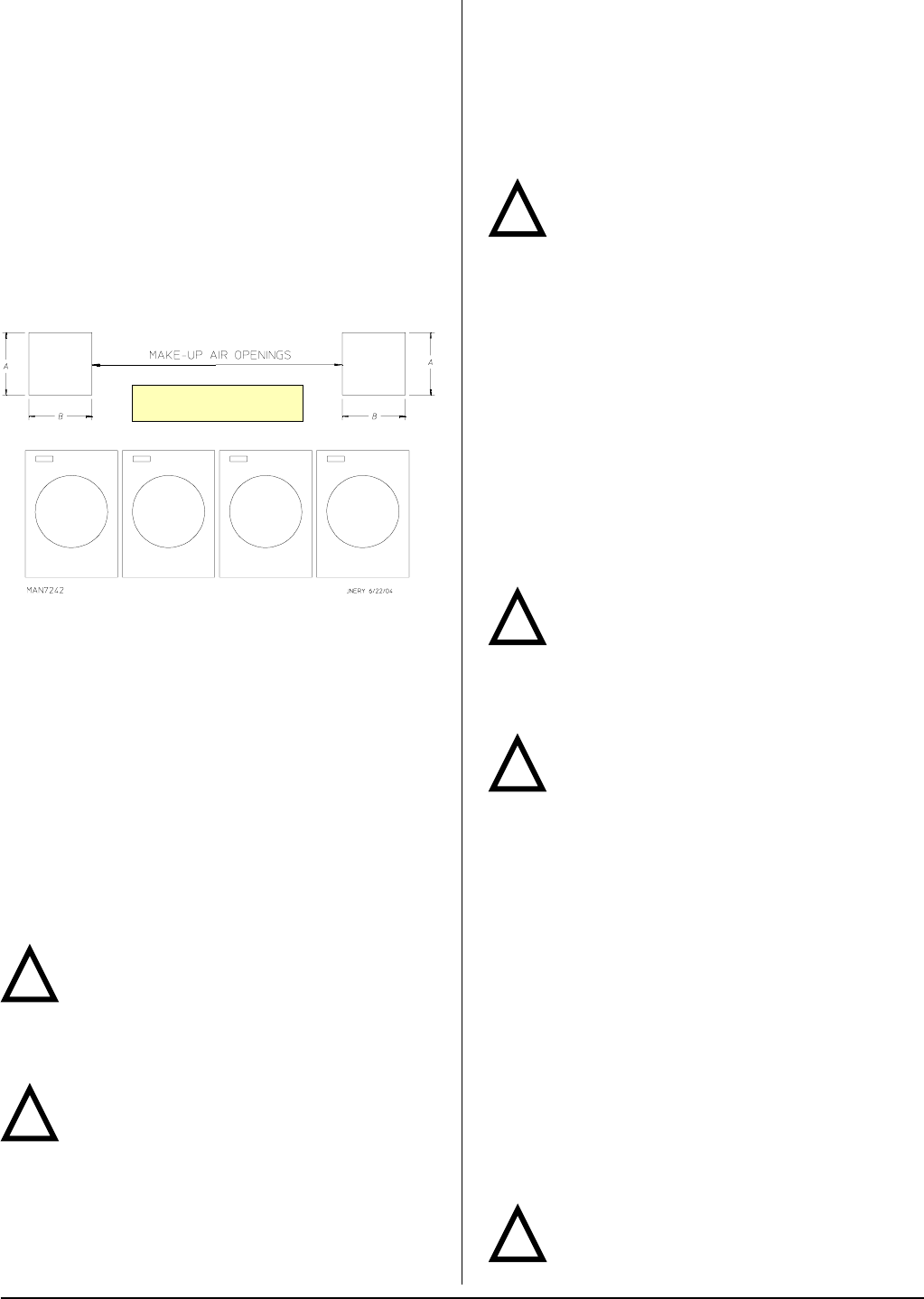
EXAMPLE: For a bank of 4 dryers, 2 unrestricted openings
measuring 17-inches by 18-inches (43.18 cm by 45.72 cm)
are acceptable.
Allowances must be made for remote or constricting
passageways or where dryers are located at excessive
altitudes or predominantly low pressure areas.
Impor tant
Make-up air must be provided from a source free
of dry cleaning solvent fumes. Make-up air that is
contaminated by dry cleaning solvent fumes will result in
irreparable damage to the motors and other dryer
components.
Note
Component failure due to dry cleaning solvent
fumes will void the warranty.
A = 17-inches (43.18 cm)
B = 18-inches (45.72 cm)
!
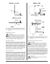
Exhaust Requirements _______________
Exhaust ductwork should be designed and installed by a
qualified professional. Improperly sized ductwork will create
excessive back pressure, which results in slow drying,
increased use of energy, and shutdown of the burner by the
airflow (sail) switch, burner hi-limits, or lint chamber hi-limit
protector thermostat. The dryer must be installed with a proper
exhaust duct connection to the outside.
Caution
This dryer produces combustible lint and must
be exhausted to the outdoors.
Improperly sized or installed exhaust ductwork can create
a potential fire hazard.
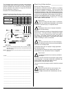
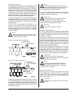
The ductwork should be laid out in such a way that the
ductwork travels as directly as possible to the outdoors with
as few turns as possible. Single or independent dryer venting
is recommended. It is suggested that the use of 90° turns
be avoided; use 30° and/or 45° bends instead. The radius of
the elbows should preferably be 1-1/2 times the diameter of
the duct. All ductwork should be smooth inside with no
projections from sheet metal screws or other obstructions,
which will collect lint. When adding ducts, the duct to be
added should overlap the duct to which it is to be connected.
All ductwork joints must be taped to prevent moisture and lint
from escaping into the building. Inspection doors should be
installed at strategic points in the exhaust ductwork for
periodic inspection and cleaning of lint from the ductwork.
Important
It is recommended that exhaust or booster fans
not be used in the exhaust ductwork system.
Exhaust back pressure measured by a manometer/
magnehelic in the exhaust duct must be no less than 0
and must not exceed 0.3 in WC (0.74 mb).
Note
When the exhaust ductwork passes through a
wall, ceiling, or roof made of combustible
materials, the opening must be 2-inches (5.08 cm) larger
than the duct (all the way around). The duct must be
centered within this opening.
As per the National Fuel Gas Code, “Exhaust ducts for
type 2 clothes dryers shall be constructed of sheet metal
or other noncombustible material. Such ducts shall be
equivalent in strength and corrosion resistance to ducts
made of galvanized sheet steel not less than 26 gauge
(0.0195-inches [0.50 mm]) thick.”
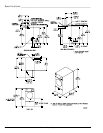
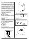
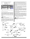
Outside Ductwork Protection
To protect the outside end of the horizontal ductwork from the
weather, a 90° elbow bent downward should be installed
where the exhaust exits the building. If the ductwork travels
vertically up through the roof, it should be protected from the
weather by using a 180° turn to point the opening downward.
In either case, allow at least twice the diameter of the duct
between the duct opening and the nearest obstruction (refer
to the diagram).
Important
Do not use screens, louvers, or caps on the
outside opening of the exhaust ductwork.
!
!