


113610-1 www.amdry.com 19
!
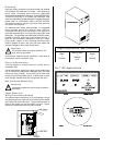
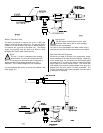
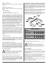
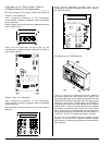
The water connection for the manual bypass is made to the
“T” or “three way” fitting, which has a 3/8” F.P.T. and a coupling
must be used to provide the minimum 1/2-inch (12.7 mm)
supply (feed) line.
If the rear area of the dryer or the water supply is located in an
area where it will be exposed to cold/freezing temperatures,
provisions must be made to protect these water lines from
freezing.
Electrical Requirements
No independent external power source or supply connection
is necessary. The 24-volt power to operate the fire
suppression system is accomplished internally in the dryer
(from the dryer controls).
Warning
Electrical power must be provided to the dryer at
all times. If the main electrical power supply to
the dryer is disconnected, the fire suppression system is
inoperative!!
Preparation for Operation/Start-Up ___
The following items should be checked before attempting to
operate the dryer:
• Read all “CAUTION,” “WARNING,” and “DIRECTION”
labels attached to the dryer.
• Check incoming supply voltage to be sure that it is the
same as indicated on the data label. In the case of 208
VAC or 240 VAC, the supply voltage must match the
electric service exactly.
• GAS MODELS – Check to ensure that the dryer is
connected to the type of heat/gas indicated on the dryer
data label.
• GAS MODELS – Be sure that all gas shutoff valves are
in the open position.
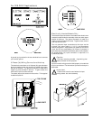
• GAS AND ELECTRIC MODELS – The sail switch
damper assembly was installed and adjusted at the
factory prior to shipping. However, each sail switch
adjustment must be checked to ensure that this
important safety control is functioning. (Refer to Sail
Switch Adjustment in the Preoperational Test section).
• Be sure all back panels (guards) and electric box
covers are in place.
• Be sure the service doors are closed and securely in
place.
• Be sure the lint door/drawer is securely in place.
• Rotate the tumbler (drum) by hand to be sure it moves
freely.
• Check bolts, nuts, screws, terminals, and fittings for
tightness and security.
• STEAM MODELS – Check to ensure that a clean, dry,
regulated air supply (80 psi [5.51 bar]) is on the dryer
(with air-operated damper system only).
• STEAM MODELS – Check to ensure all steam shutoff
valves are open.
• STEAM MODELS – Check steam damper operation.
• Check tumbler bearing setscrews to ensure they are all
tight.
!
!
!
• Check that the vent is connected to the dryer and is
exhausted to the outdoors.
Preoperational Test ___________________
All dryers are thoroughly tested and inspected before leaving
the factory. However, a preoperational test should be
performed before the dryer is publicly used. It is possible
that adjustments have changed in transit or due to marginal
location (installation) conditions.
Turn on electric power to the dryer.
Refer to the Operating Instructions for starting your particular
model dryer.
Gas Dryers
Open all shutoff valves.
When a gas dryer is first started (during initial start-up), it has
a tendency not to ignite on the first ignition attempt. This is
because the gas supply piping is filled with air, so it may take
a few minutes for the air to be purged from the lines.
Note
During the purging period, check to be sure that
all gas shutoff valves are open.
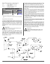
Gas dryers are equipped with a DSI system, which has
internal diagnostics. If ignition is not established within 3
attempts, the heat circuit in the DSI module will “lockout”
until it is manually reset. To reset the DSI system, open
and close the main door and restart the dryer.
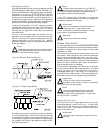
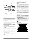
A gas pressure test should be taken at the gas valve pressure
tap of each dryer to ensure that the water column pressure is
correct and consistent.
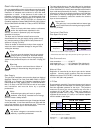
Note
Water column pressure requirements (measured
at the pressure tap of the gas valve body):
Natural Gas ___ 3.5 in WC (8.7 mb)
L.P. Gas_______ 10.5 in WC (26.1 mb)
Impor tant
There is no regulator provided in an L.P. dryer.
The water column pressure must be regulated at
the source (L.P. tank), or an external regulator must be
added to each dryer.
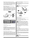
Steam Dryers
Check to ensure that steam damper is functioning properly.
The steam damper should not “slam” (open or closed) when
it reaches the end of (piston) travel. Additionally, the steam
damper should not bind and/or stop during travel. If either of
these conditions occur, the flow control must be adjusted.
Refer to the Steam Damper Air Piston (Flow Control)
Operation Adjustment instructions in the steam information
section.