


113610-1 www.amdry.com 15
!
Piping/Connections
All components/materials must conform to National Fuel Gas
Code Specifications ANSI Z223.1-LATEST EDITION, or in
Canada, CAN/CGA-B149.1-M91 (Natural Gas) or CAN/CGA-
B149.2-M91 (L.P. Gas) or LATEST EDITION (for General
Installation and Gas Plumbing), as well as local codes and
ordinances and must be done by a qualified professional. It
is important that gas pressure regulators meet applicable
pressure requirements, and that gas meters be rated for the
total amount of all the appliance Btu being supplied.
The dryer is provided with a 1/2” N.P.T. inlet pipe connection
located at the upper left rear of the dryer. The minimum pipe
size (supply line) to the dryer is 1/2” diameter. For ease in
servicing, the gas supply line of each dryer must have its
own shutoff valve.
The size of the main gas supply line (header) will vary
depending on the distance this line travels from the gas
meter or, in the case of L.P. gas, the supply tank, other gas-
operated appliances on the same line, etc. Specific
information regarding supply line size should be determined
by the gas supplier.
Note
Undersized gas supply piping can create a low or
inconsistent pressure, which will result in erratic
operation of the burner ignition system.
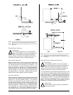
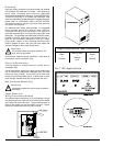
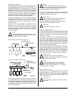
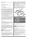
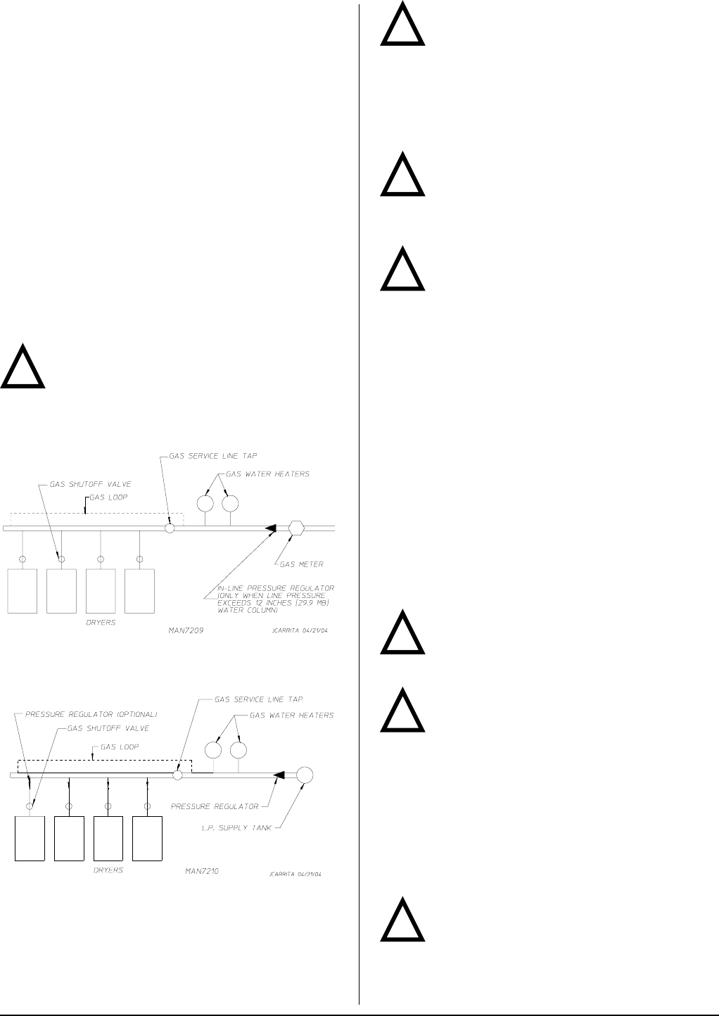
Typical Natural Gas Installation
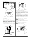
Typical L.P. Gas Installation
!
!
!
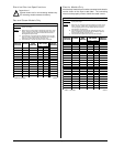
Note
A water column test pressure of 3.5 in WC (8.7
mb) for natural gas and 10.5 in WC (26.1 mb) for
L.P. dryers is required at the gas valve pressure tap of
each dryer for proper and safe operation.
A 1/8” N.P.T. plugged tap, accessible for a test gauge
connection, must be installed in the main gas supply line
immediately upstream of each dryer.
Important
Pipe joint compounds that resist the action of
natural gas and L.P. gas must be used.
Test all connections for leaks by brushing on a soapy
water solution (liquid detergent works well).
Warning
Never test for leaks with a flame!!!
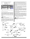
Steam Information ___________________
It is your responsibility to have all plumbing connections made
by a qualified professional to ensure that the steam plumbing
installation is adequate and conforms with local and state
regulations or codes.
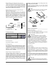
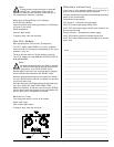
Care must be exercised when leveling steam dryers into
final position. After leveling the dryer, check the downward
pitch of the heat exchanger from front to rear with a level.
Likewise, check the downward pitch of the return condensate
manifold toward its outlet part. Absence of these downward
pitches will result in probable water hammer and premature
heat exchanger fracture and leakage.
The presence of condensate in the steam will cause water
hammer and subsequent heat exchanger failure. The steam
supply connection must be taken from the top of a
well-dripped steam main. If the supply run-out to the dryer
exceeds 20 feet (6.096 meters), it should be dripped just
before the control valve with a proper trap and dirt pocket.
Important
Failure to comply with the requirements
stipulated in this manual can result in component
failure, which will void the warranty.
Note
The dryer is manufactured with a pneumatic
(piston) damper system, which requires an
external air supply of 0.75 cfh @ 80 psi +/- 10 psi (0.02
cmh @ 5.51 bar +/- 0.69 bar).
Steam Coil pH Level
The normal pH level for copper type steam coils must be
maintained between a value of 8.5 to 9.5. For steel type
steam coils the pH level must be maintained between a
value of 9.5 to 10.5. These limits are set to limit the acid
attack of the steam coils.
Impor tant
Coil failure due to improper pH level will void the
warranty.
!
!
!
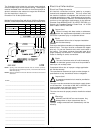
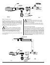
Consistent gas pressure is essential at all gas connections.
It is recommended that a 3/4-inch (19.05 mm) pipe gas loop
be installed in the supply line servicing a bank of dryers. An
in-line pressure regulator must be installed in the gas supply
line (header) if the (natural) gas pressure exceeds 12.0 in
WC (29.9 mb) pressure.