


113610-1 www.amdry.com 17
!
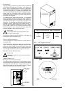
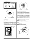
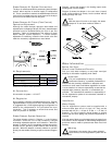
Steam Damper Air System Connections
The dryer is manufactured with a pneumatic (piston) damper
system, which requires an external supply of compressed
air. The air connection is made to the steam damper solenoid
valve, which is located at the rear inner top area of the dryer
just in front of the electric service relay box.
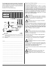
Steam Damper Air Piston (Flow Control)
Operation Adjustment
Although the steam damper operation was tested and
adjusted prior to shipping at 80 psi (5.51 bar), steam damper
operation must be checked before the dryer is put into
operation. Refer to Preoperational Test section to check
steam damper system operation. If steam damper
adjustment is necessary, locate the flow control valve and
make the necessary adjustments as noted below.
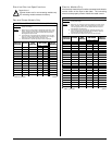
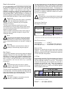
Air Requirements
Shaded areas are stated in metric equivalents
Air Connection
Air connection to system – 1/8” N.P.T.
Air Regulation
No air regulator or filtration is provided with the dryer. External
regulation/filtration of 80 psi (5.51 bar) must be provided. It
is suggested that a filter/regulator/gauge arrangement be
added to the compressed air line just before the dryer
connection. This is necessary to ensure that correct and
clean air pressure is achieved.
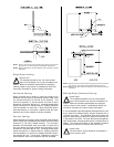
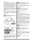
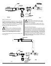
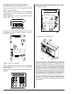
Steam Damper System Operation
The steam damper shown in Diagram 1 in the following
illustration, allows the coil to stay constantly charged
eliminating repeated expansion and contraction. When the
damper is opened, the air immediately passes through the
already hot coil, providing instant heat to start the drying
process. When the damper is closed, ambient air is drawn
directly into the tumbler, allowing a rapid cool down (Diagram
2).
Compressed Air Supply Air Pressure
Normal 80 psi
5.51 bar
Minimum Supply 70 psi
4.82 bar
Maximum Supply 90 psi
6.21 bar
Diagram 1 shows the damper in the heating (open) mode,
allowing heat into the tumbler.
Diagram 2 shows the damper in the cool down (closed)
mode, pulling ambient air directly into the tumbler without
passing through the coils.
Note
With the dryer off or with no air supply, the steam
damper is in cool down mode as shown in
Diagram 2.
Water Information ____________________
Before You Start
Check Local Codes and Permits
Call your local water company or the proper municipal
authority for information regarding local codes.
Important
It is your responsibility to have all plumbing
connections made by a qualified professional to
ensure that the plumbing installation is adequate and
conforms to local, state, and federal regulations or codes.
It is the installer’s or owner’s responsibility to see that the
required water pressure, pipe size, or connections are
provided. The manufacturer assumes no responsibility if
the fire suppression system is not connected, installed, or
maintained properly.
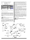
Installation
Water Supply
The fire suppression system must be supplied with a
minimum water pipe size of 1/2-inch (12.7 mm) and be
provided with 40 psi +/- 20 psi (2.75 bar +/- 1.37 bar) of
pressure. For use of optional manual bypass, a second
source with the same piping and pressure requirements is
required.
If the rear area of the dryer or the water supply is located in an
area where it will be exposed to cold/freezing temperatures,
provisions must be made to protect these water lines from
freezing.
Warning
If the water in the supply line or water solenoid
valve freezes, the fire suppression system will be
inoperative!!
!
!