


24 American Dryer Corp. 113610-1
Procedure for Functional Check
of Replacement Components ________
Microprocessor Controller (Computer) Board
Phase 7 Coin Models
Upon completing installation of the replacement
microprocessor controller (computer) board, reestablish
power to the dryer.
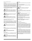
Start the drying cycle by pressing any temperature selection
keys (HI, MED, or LO).
Phase 7 Non-Coin Models
Upon completing installation of the replacement
microprocessor controller (computer) board, reestablish
power to the dryer.
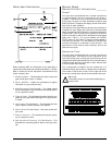
Start the drying cycle by pressing any of the preset cycles in
letters A-F.
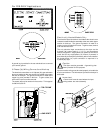
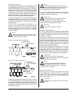
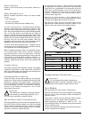
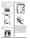
Verify that the applicable indicator lights on the
microprocessor controller (computer) board are lit. (Refer to
the illustration below.)
Verify that the applicable indicator lights on the
microprocessor controller (computer) board are lit. (Refer to
the illustration below.)
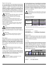
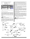
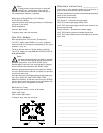
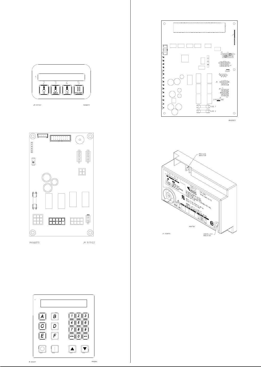
For Models with DSI Module
Theory of Operation: Start the drying cycle. When the
gas burner ignites within the chosen trial for ignition time
(8-seconds), the flame sensor detects gas burner flame and
signals the DSI module to keep the gas valve open as long
as there is a call for heat. The DSI module will “LOCKOUT”
if the gas burner flame is not sensed at the end of the trial for
ignition period. The trial for ignition period will be repeated
for a total of 3 retries/trials (the initial try and 2 more retries/
trials). If the flame is not sensed at the end of the third retry/
trial (inter-purge period of 30-seconds), the DSI module will
“LOCKOUT” (a red L.E.D. diagnostic indicator will flash).
An unlit red L.E.D. diagnostic indicator indicates normal
operation. A lit green L.E.D. diagnostic indicator indicates
dryer controller is calling for heat and that all interlocks have
been satisfied.