


30
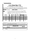
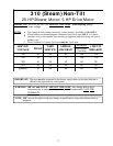
2. Technical Gas Data
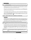
a. Gas Specifications
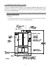
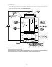
b. Gas Connections
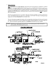
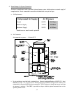
Run a 1-1/2” pipe from the main gas header to the dryer. There are two (2) 1-1/4” gas pipe connections
at the top of the dryer. The dryer has two (2) gas burner boxes and each one (1) has its own 1-1/4” gas
connection.
Inlet connection -----------two (2) 1-1/4” N.P.T.
Inlet Supply Size -----------1-1/2” N.P.T. (minimum)
BTU/hr input (per dryer) -1,125,000 (283,500 kcal/hr)
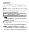
1) Natural Gas
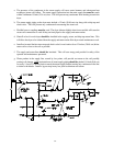
Pressure regulation is controlled by both gas valve’s internal regulators. Incoming supply pressure
must be consistently between a minimum of 6.0 inches (14.92 mb) water column (W.C.) and a
maximum of 12.0 inches (29.9 mb) water column.
2) Liquid Propane (L.P.) Gas
Dryers made for use with L.P. gas have both of their gas valves internal pressure regulators blocked
open so that the gas pressure must be regulated upstream of the dryer. The pressure is measured
at each gas valve pressure tap must be a consistent 10.5 inches (26.1 mb) water column. There is
no regulator or regulation provided in an L.P. gas dryer. The water column must be regulated at the
source (L.P. tank) or external regulator/regulation must be added to each dryer.
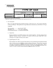
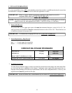
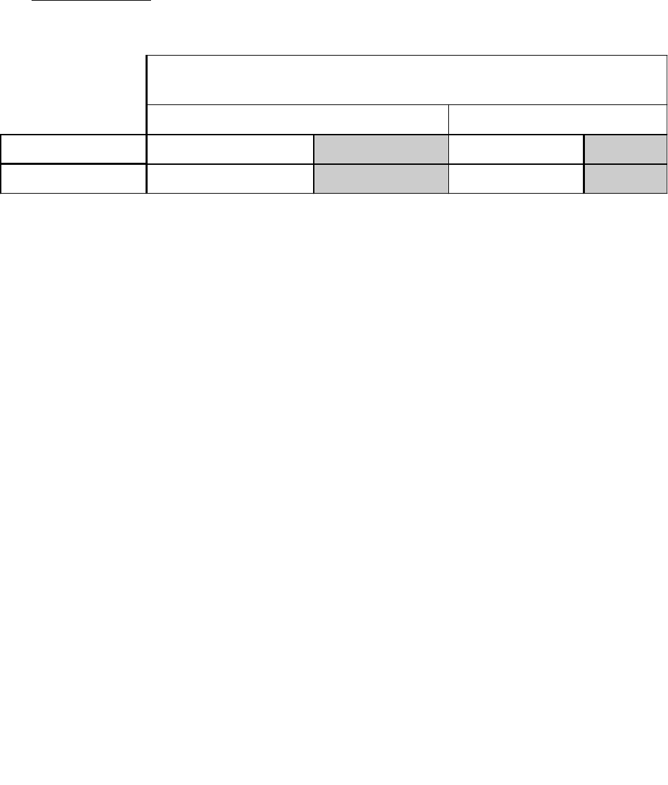
TYPE OF GAS
NATURAL LIQUID PROPANE
Manifold Pressure* 3.5 inches W.C. 8.7 mb 10.5 inches W.C. 26.1 mb
In-Line Pressure 6.0 - 12.0 inches W.C. 14.92 - 29.9 mb 10.5 inches W.C. 26.1 mb
Shaded areas are stated in metric equivalents
* Measured at outlet side of gas valve pressure tap when gas valve is on.