


51
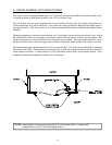
E. STEAM DAMPER ACTUATOR SYSTEM
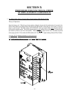
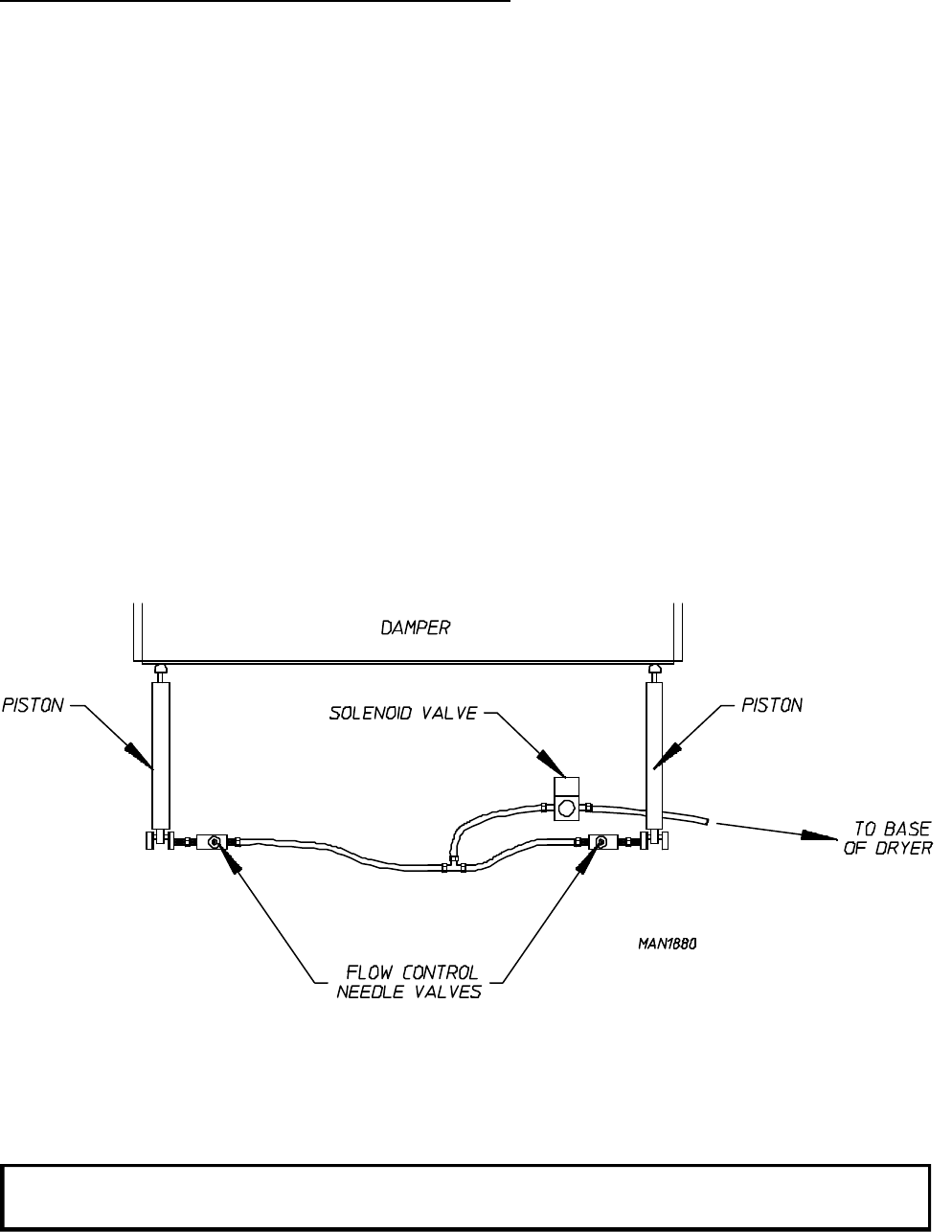
The system consists of a hinged damper plate, two (2) pneumatic pistons (each with its own airflow needle valve)
to control the speed of both pistons actuation, and a 24 volt solenoid valve.
On a call for heat, a 24 volt signal is applied to the 3-way/2-position solenoid valve. This signal switches the valve
so that compressed air is sent to the pistons. The piston rods extend, pushing the hinged steam damper plate to
the opened position. This allows room air to be drawn through the hot steam coil and then through the basket
(tumbler).
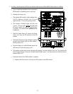
When the temperature set point has been reached, the 24 volt signal is removed from the solenoid valve, so that
the solenoid valve blocks the air supply to the pistons, and the air in the pistons is bled to the atmosphere. The
springs in the pistons now retract the piston rods, closing the steam damper: The steam damper plate now covers
the steam coil and allows room air to bypass the coil before entering the basket (tumbler) for a rapid cool down.
The steam damper plate should open and close slowly and smoothly. The speed can be modulated by adjusting
both needle valve knobs. Turning the knob clockwise (CW) restricts the compressed airflow and slows down the
steam damper movement. Counterclockwise (CCW) adjustment speeds up the steam damper motion. Upon
completion of adjustment, tighten the needle valve’s locking nut.
NOTE: Turning knob on flow control clockwise (CW) will restrict airflow. Turning knob
counterclockwise (CCW) will allow higher airflow.