


Installation
31
802031
© Copyright, Alliance Laundry Systems LLC – DO NOT COPY or TRANSMIT
Figure 31
Figure 32
H318I
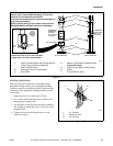
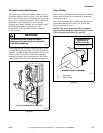
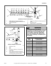
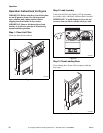
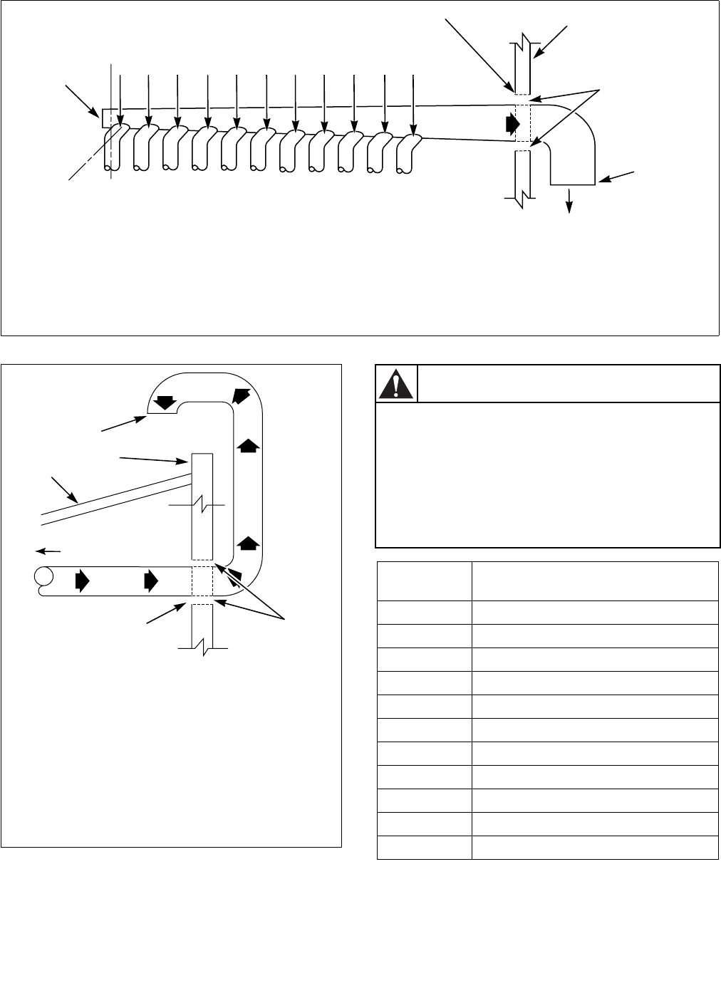
1 NOTE: Where the exhaust duct pierces a
combustible wall or ceiling, the opening must be
sized per local codes.
3 51 mm (2 in.) Minimum or Clearance per Local
Codes
4 No Screen or Cap
2 Wall 5 Clean Out Cover – Inspect Monthly
2
3
4
EXHAUST
OUTLET
KJIHGFEDCBA
5
30°
1
AIR
FLOW
HORIZONTAL EXHAUST INSTALLATION
EXHAUST AIR FLOW
MAXIMUM LENGTH OF DUCT
9.1 m (30 feet)
H319I
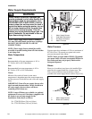
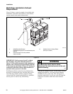
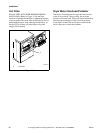
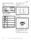
1 No Screen or Cap
2 Roof
3 Wall
4 51 mm (2 in.) Minimum or Clearance Per
Local Codes
5 NOTE: Where the exhaust duct pierces a
combustible wall or ceiling, an opening must
be sized as shown or per local codes.
1
3
2
4
5
CONNECT TO DRYER
VERTICAL EXHAUST INSTALLATION
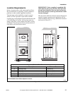
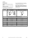
Duct
Station
Minimum Diameter of
Collector Duct
A 102 mm (4 inches)
B 203 mm (8 inches)
C 229 mm (9 inches)
D 254 mm (10 inches)
E 279 mm (11 inches)
F 305 mm (12 inches)
G 326 mm (13 inches)
H 356 mm (14 inches)
I 381 mm (15 inches)
J 381 mm (15 inches)
K 406 mm (16 inches)
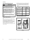
To reduce the risk of fire and the
accumulation of combustion gases, DO NOT
exhaust dryer air into a window well, gas
vent, chimney or enclosed, unventilated
area, such as an attic, wall, ceiling, crawl
space under a building or concealed space
of a building.
W045
WARNING