


Installation
23
802031
© Copyright, Alliance Laundry Systems LLC – DO NOT COPY or TRANSMIT
Figure 21
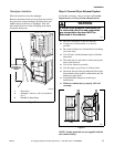
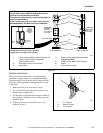
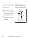
Earthing Instructions
This dryer must be connected to an earthed metal,
permanent wiring system; or an equipment-earthing
conductor must be run with the circuit conductors and
connected to the equipment-earthing terminal or lead
on the dryer.
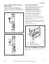
1. Remove access cover from rear of dryer.
2. Use a strain relief and insert end of power cord
through power supply hole.
3. Use the three screws from the envelope located in
the cylinder to attach the power cord wires to the
terminal block.
4. Tighten all screws and reinstall access cover
removed in step 1.
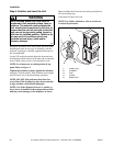
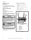
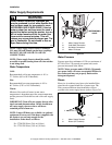
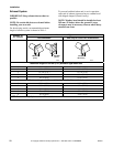
Figure 22
D816I
1 3 Wire Grounded Neutral 230 Volt, 60 Hertz AC
1 Phase Service Entrance Switch Box
(Refer to NOTE above)
4 Metallic or Non-Metallic Sheathed Cable
(Copper Wire Only)
5 Pigtail to Dryer (Refer to NOTE above)
2 30 Ampere Fuses or Circuit Breaker 6 Neutral
3 Neutral Wire 7 Terminal Block in Dryer
NOTE: The power cord (pigtail) is NOT supplied with the
electric dryer. Type of pigtail and gauge of wire must
conform to local codes and instructions.
The method of wiring the dryer is optional and subject to
local code requirements.
NOTE: Connect the dryer to the power supply with the
MAXIMUM RATED VOLTAGE listed on the nameplate.
1
2
3
4
5
6
7
POWER SUPPLY POWER SUPPLY
INTERMEDIATE
FUSE BOX (May
be omitted if
service entrance
box is fused)
WALL RECEPTACLE
PIGTAIL CONNECTION
L1 L2 L1 L2
DIRECT CONNECTION
INTERMEDIAT
E
SHUT-OFF BOX
(May or may
not be fused)
120 ± 12
V.A.C.
A typical
30 Amp
Three-wire
Receptacle
NEMA Type
10-30R
120 ± 12
V.A.C.
230 ± 12
V.A.C.
NOTE: Use COPPER WIRE only.
Shorter than 4.5 m (15 ft.) use 10 A.W.G.
Longer than 4.5 m (15 ft.) use 8 A.W.G.
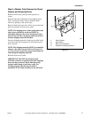
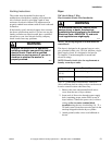
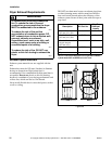
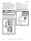
D286I
1 “L1” Terminal
2 Neutral Terminal
3 “L2” Terminal
1
3
2