


Installation
25
802031
© Copyright, Alliance Laundry Systems LLC – DO NOT COPY or TRANSMIT
Location Requirements
Select a location with a solid, sturdy and level floor.
Do not install unit on carpeting, soft tile, pedestal, a
platform or other weakly supported structures.
The unit must not be installed or stored in an area
where it will be exposed to water and/or weather.
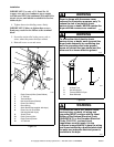
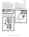
Leveling legs can be adjusted from inside the unit with
a 7/8 inch deep well socket. All four legs must rest
firmly on the floor so the weight of the unit is evenly
distributed. The unit must not rock and must be level
from side-to-side and front-to-back.
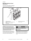
IMPORTANT: Unless completely assembled, DO
NOT slide the unit across the floor. DO NOT slide
the unit more than four feet once the leveling legs
have been extended, as the legs and the base could
become damaged.
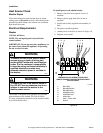
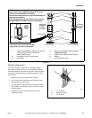
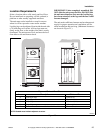
The unit needs sufficient clearance and an adequate air
supply for proper operation and ventilation, and for
easier installation and servicing. (Minimum clearances
are shown in Figure 25.)
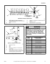
Figure 25
NOTE: Shaded areas indicate adjacent structure.
SWD698N
SWD698N
A B
C
D
E
E
Dryer and Exhaust Duct Clearances
Area Description Minimum Clearance
A Left Dryer Side 0 mm (0 in.)
B Right Dryer Side 25.4 mm (1 in.)
C Dryer Top 152.4 mm (6 in.)
D Dryer Rear 102 mm (4 in.)
E Exhaust Duct Clearance to Combustible Materials 51 mm (2 in.)